Eltro-Zeiss Fero Z-51 NV scope in detail

The #1 community for Gun Owners of the Northeast

Member Benefits:

  • No ad networks!
  • Discuss all aspects of firearm ownership
  • Discuss anti-gun legislation
  • Buy, sell, and trade in the classified section
  • Chat with Local gun shops, ranges, trainers & other businesses
  • Discover free outdoor shooting areas
  • View up to date on firearm-related events
  • Share photos & video with other members
  • ...and so much more!
  • Combloc

    Stop Negassing me!!!!!
    Nov 10, 2010
    7,268
    In a House
    I've decided to do another of my long and dry "in detail" posts so be prepared to be bored out of your skull. This time it's on the Fero Z51 NV scope and, as usual, it's copyright (2013) so please don't use my text or photos without permission. These scopes showed up in some numbers on the surplus market in 2011 for a reasonable price (IIRC, I paid under 450 for mine shipped) and were available for a while. I think that they are still available in a few places but prices are rising steadily and these will soon be relegated to collector rather than useful tool status. And that's too bad because they were built to use and use hard, not sit tucked away in a closet and only be handled with care for a show and tell session. Even though their availability has passed its zenith, I still see questions about them from time to time on forums that I visit and so I decided to post some detailed pictures for folks who will want to know about these old clunkers in the future when they simply aren't available any longer. It will take me a few posts over a few nights in order to get this done but get it done I will so let's jump into it. The logical place to start is the case. It's made of green fiberglass with aluminum hardware and it's big and clunky but it's also extremely tough! Here's the top of the lid with it's identifying information painted on instead of being a decal like my older Eltro B8-V:


    Rear and bottom:


    And sides:


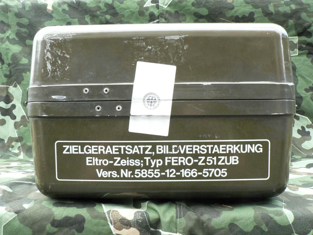
    Notice the number "11378" on the box. This was printed on paper and then taped on. This same number is stamped on the body of the scope but I have no idea what the small " (9) " means. Also not that both sides have what appears to be a seal which has of course been broken. Here's a close-up of the stamp on one of those seals:


    This stamp identifies this unit as having been assigned to Infantry Battalion 232 of the 23rd Mountain infantry Brigade based in Berchtesgaden. Neato!

    Here's the latch side of the case. I stacked an older Eltro B8-V unit (the predecessor to the Z51) on top of the one being presented here in order to show that the latches are different but otherwise the cases are nearly identical.


    You can see where there used to be a label above the handle that is now missing and there is a small red wire twisted around the handle. I have no idea what it is but it was on there when I got it and it will be on there when it leaves me. You can also see what I think is a pressure relief valve but I don't really know if that's what it is or how it works if it is!

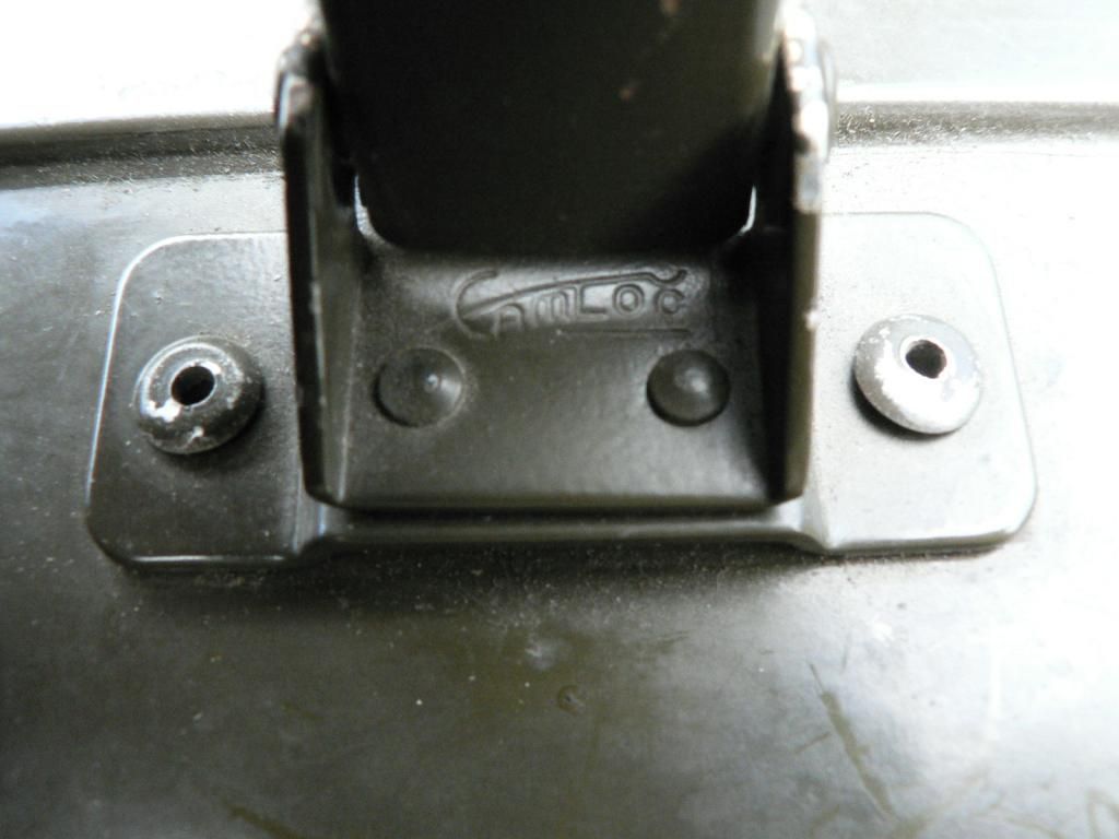
    Here are a few close-ups of a latch. They are ingenious little devils made by "Camloc" and are pressure adjustable by screwing the grabber part in or out. The latches on the older case are non-adjustable.


    Here's the case opened showing all the goodies inside:


    You can see the number "11378" again taped inside the lid and you can also see the part numbers for the foam rubber interior cushions molded into them. There is also a packing diagram/manifest sticker in the top. Let's take a look at that:


    On the left are the words "telescope equipment set" (loosely translated) with the part/inventory number for the whole unit below. Below that is a diagram of everything. To the right are four columns. The first is the position noted in the diagram. Next is the number of each item a complete set ships with. Then we have a column telling what each item is. The last column gives the inventory number for each component.

    Here's a picture showing the back of the cushion after being removed from the lid:


    Printed on a sticker attached to the lid is the part number for the case itself. Hand done in chalk on the back side of the cushion is the serial number that is stamped into the foil identification plate attached to the scope. Don't touch it as it rubs right off (I found this out the hard way). Why these scopes have two numbers identifying them is unknown to me but every one I've seen has this same setup. There must be a reason for it though.

    Here's the bottom cushion removed:


    And a little stamp on the bottom of the cushion:


    Here's a comparison shot of the older Gen0 B8-V on the right and the newer Gen 1 Z-51 on the right:


    You can easily see that the cases are very nearly identical between the two units. The older unit has foam inserts while the newer one has molded stuff that holds up better. It's almost rubber and you can tell that it was poured in a mold. I'm sure that there is a common name for the stuff but I can't think of it at the moment. Alright.....tired of looking at cases yet? I know I am. In the next post, , we move onto accessories and mounts but I'm taking a break and I'll get back to this in a bit.
     

    Combloc

    Stop Negassing me!!!!!
    Nov 10, 2010
    7,268
    In a House
    On to accessories and mounts. Let's start with the Panzerfaust mount. When this unit entered service, the Germans were using some version of Panzerfaust and the manifest label in the lid identifies the mount that was to be used on that weapon and the lower cushion has a molded area for it as well. My B8-V unit came with that mount and it fits right in the slot for it in this case. However, that is not the mount that came with this unit. Apparently, by the time this scope was made in 1978 they were using a more modern form of Panzerfaust and the mount for that was included here. It was made by HK and is painted in HK's signature blue/black paint whereas the other mounts (except for the claw mount because it is alloy) are phosphated steel. It also came with an instructional pamphlet printed by HK and dated 1979 that explains how to use the mount. I assume that instructional manuals hadn't been updated yet so they threw these updated in with each unit until manuals were reprinted. Anywho, here is the mount seen from different angles and the pamphlet:


    Here's the MG3 mount:


    Not much to say about it really. You can see the allen screws used to adjust windage and elevation for zeroing and you can see that it (and the Panzerfaust mount already shown) has a rail screwed on top of it for the quick connect clamp which will be shown next.

    Here is rail and the quick connect. Left side view:


    Right side (quick connect shown only as the rail looks identical from each side):


    Top:


    Bottom:


    Connected and locked:


    There are two ways to attach the scope to any particular mount. If you attach the quick connect to the scope and a rail to a mount, you can simply loosen the lever and slide the scope off the rail of one weapon and slide it onto the rail of another to be locked back down. The problem with this is that it raises the scope up off the weapon an extra inch plus. It already sits crazy high and this setup just exacerbates the problem. The other way to do it is to remove the rail from the mount and the quick connect from the scope. Then you screw the scope directly to the mount. The problem with this setup is that you now have a dedicated scope with mount that can only be used on one weapon system. That isn't a problem for me as I don't see myself having opportunity to use it on an MG3 or a Panzerfaust in the foreseeable future! So I just have my scope screwed to the claw mount for rifle use. The claw mount is a typical one as used on any Cetme/HK/PTR style rifle so I'm not going to go into detail on it. The only difference here is that there is no serial number on the mount for obvious reasons. One last note on mounts/rails/quick connect. The numbers that you see on them are not serial numbers. They are part/inventory numbers and they coincide with the numbers shown on the diagram inside the lid. Think about going to an auto parts store and ordering a part for your car. Everything is done by part numbers and the same applies here.

    Here we see a screwdriver, lens cleaning cloth folded up in its ziplock bag (with part number printed on it...those tidy little Germans!), 4mm wrench and extra rail/mount screws with lock washers. There is supposed to be a 2mm wrench too according to the manifest but I didn't get one if it was supposed to be there.


    Here's the 4mm wrench with it's size and manufacturer markings on it. They painted the stamp in, not me. Just wow....someone at UNBRAKO thought it was necessary to paint the stamp in on what is essentially a throwaway item before it left the factory....really?


    Carry bag and strap. Notice the part numbers:


    Bag turned inside out to show plastic objective lens protector and canvas ocular lens protector. You can also see the canvas reinforcing strap that runs along the top of the bagin between the d-rings:


    YKK zipper in bottom of bag with broken tip of pull fob:


    Bag with scope stowed and carry strap attached to d-rings:


    Detail of strap connector. The black circle is a rivet, not a snap.


    And that's it for tonight. Tomorrow, I will cover the scope itself and throw in a couple comparison shots of it to its Soviet counterpart to finish up. Thanks for your time!
     

    Combloc

    Stop Negassing me!!!!!
    Nov 10, 2010
    7,268
    In a House
    I'll finish up tonight by going over the scope itself. I haven't taken it apart and I have no plans to do so unless it goes kaplooee on me but I have taken an Oldeft unit apart and I get the feeling that they are very similar internally after comparing the two. Even the shade knob on the Oldeft had the same scraping dragging feeling as the one on this scope. Even these scopes are Gen 1, they are far superior to what you would expect out of a typical Gen 1 unit. I can't see any fisheye ore other distortion but you might see it if you looked at one of those grid test card thingees. The resolution is very good and sparkles are at a minimum. It's what you would expect out of a German shop. I'm terrible at taking pictures so I can't get good shots looking through my scope to post but if you look around on youtube there are a few good videos looking through one. However, even they don't show just how good the image looks in reality. Ok, we'll start off with a few general views.

    Here's the left side:


    Starting at the back, we have the removeable green rubber eyecup. It's tethered to the scope body with a plastic string so that it doesn't go missing on you. Next is the ocular lens. Notice that it has a diopter adjustment in case you wear glasses. The two green rings in front of the ocular lens are threaded connectors holding it to the scope body. One screws down against the other acting as a locknut and you use special wrench that locks into the holes to tighten and loosen the rings. Next we have the main body of the scope itself. It's some sort of molded aluminum alloy. Inside it rest the electronics and the three stage intensifier tube. It also has a battery box molded into the other side. The silver rectangle is the ID plate and I'll give you more info on that in a bit. Moving forward, we see three knobs with alien writing on them. I'll discuss what they do in a bit as well. Attached to the front of the scope body by five allen screws is the objective lens housing. The rubber lens cap affixes to this.

    Right side showing the battery box. This is molded into the scope body not attached to it:


    Rear end showing the eyecup with its light shutter closed:


    This shutter is designed so that it opens up as you press your head against it. The purpose of it is to hide the green glow of the ocular lens.

    Eyecup removed showing the lens:


    The green circle to the right of the lens is the battery box door further up the body. You can also clearly see the plastic tether holding running between the eyecup and the scope body. It's essentially heavy gauge fishing line.

    Here's a detail shot of the tether:


    Looking down into the removed eyecup you can see the shutters. They are molded as part of it and are not removable unless you break out a knife. I've seen this done but I'm not.


    The black ring with three screws is the part that connects to the ocular lens. It simple snaps on. The three other holes in the black ring are air vents so that you don't suction your eye to the thing.

    Here I've pressed down on the eyecup popping the shutters open:


    Here's a detail of the diopter adjustment markings:


    Notice that the ribbed adjustment ring has a little nub on it. When the diopter adjustment is set to zero, this nub lines up with a corresponding nub on the nonmoving part. I guess that the purpose of these is so that you can tell by feel when you are at zero adjustment. However, that seems redundant to me because there is a click stop at zero anyways. Maybe there is another purpose for it but I can't think of any. This picture also illustrates the fact that the green paint finish on these scopes is stippled, not smooth.

    Here's the front of the scope with the lens cap in place:


    Notice that there are three small holes in it. These holes allow light in so that you can use the unit during the day. The image quality is nowhere near as good as you get with the lens cap removed at night but they get the job done. The only reason to have it on during the day anyways is to sight it in. You probably already know this but NEVER EVER remove the lens cap during the day or in a bright area (such as in your dining room with the lights on!) at night with the unit powered on. I guarantee that you will blow it out and you will now have an absolutely useless hunk scrap. Also, never remove this cover for at least ten minutes or longer after switching the unit off as the tube still has residual charge and is still light sensitive. Also, the two rubber straps holding this cap to the bell housing are old. Don't pull straight out on the cover and stretch them or they are very likely to snap. Just pull up on the left side enough for the cover to clear the housing and gently work it over and fold it down along the left side. The rubber ring around the edge of housing does not come off. The lens cover fits down into this rubber ring so you are pulling on the lip INSIDE the front of the cover where the asterisk shaped reinforcement ribs are, not the lip of the rubber ring outside of the housing. I hope that makes sense.

    Lens cover removed.....dusty I know. I don't get over concerned about that as it doesn't affect image quality. At first, I tried to keep it spotless but it's a losing battle. Of course, the glass is coated so don't touch it unless you want fingerprints permanently etched into it. Be careful removing and replacing the lens cover too as the rubber straps tend to make it hit the glass, leaving a mark.


    A couple close up shots of the objective lens....nice, pretty, dusty German glass:


    That's it for this post. One or two more and I'm done!
     

    Combloc

    Stop Negassing me!!!!!
    Nov 10, 2010
    7,268
    In a House
    While we're up here, lets look at the rest of the bell housing. First is the right side of it:


    To the left of the picture is the front of the battery box. I think that the rib running along the housing has something to do with the reticle but I'm not sure about that and I'm not ripping it apart to find out! Below the rib is an attachment point for the lens cover band. If you remove the screw, the metal plate comes off and then you can pop the rubber band off the nub to replace the lens cover should this band snap......give it time and it will. Just above the rib is a rubber cover for the elevation adjustment screw. Also visible in this picture are several of the allen screws that hold the housing to the scope body.

    Here we see the rubber cover folded back revealing the elevation adjustment screw:


    The 4mm wrench is used here. I used to know which way was which for adjustment on this thing but I've forgotten. I was crazy lucky and had to do absolutely zero adjustment. I simply took it out of the box, clamped it to my rifle and it was dead on zero. What are the chances of that?? Unfortunately, very few of these scopes came with a manual when they were imported and mine was no exception. I'd like to find an original simply for collection purposes so look me up if you have one that you are willing to part with. RTG parts has a nice translated one for sale on their website but I'd like to have an original just because.

    This is the top of the housing:


    You can see the other lens cover strap attachment point and two more of the allen screws that hold the housing to the body. The four rectangles are plastic caps that cover the attachment points for the IR illuminator. A bracket somehow attaches to these lugs and the same illuminator that affixes to the earlier B8-V scope is used for times when available light is near zero. I have never seen one of these brackets for sale or in pictures but I know that they exist. Maybe I'll find one someday. In between the two rear lugs is the rubber cover for the windage adjustment screw. You can also see the reticle brightness knob which we will look at more closely later.

    A shot of the windage cover folded back revealing the screw:


    Next is the battery box. The scope uses two "C" batteries and the box shows you which way they go in. It's molded right into the side of the box so you're an idiot if you put them in wrong. Here the cover is closed:


    You simply push down on the black button and the door will swing down....or fly down if you have batteries installed.

    And the cover open:


    Not much more to be said about that.

    Next are two allen bolts on the housing. One is up top and one is underneath:


    I don't know what their purpose is but I seem to recall reading somewhere once that they were used for testing the unit after assembly. I do know that they are bolts and that they are removable even though I'm not doing it!

    This number is stamped into the rear mount attachment lug on the scope body. It is one of two serial numbers. Why there are two I don't know but every one that I've seen is this way. The older B8-v is the same way. It's the same number that is attached to the outside of the case and the inside top cushion of the case.


    The foil ID plate:


    This plate is covered in a plastic film. When they stamped the serial number and date into the foil, it pierced the film and you can see that it is peeling around the numbers. Starting at the top of the plate , we have the part/assembly number for the entire scope. Next line is the model designation. Below that is the description line telling you what the object you are holding in your hand is. This comes in handy if you are from an alien planet and have never seen a rifle scope before. Next we have the serial number. This number was seen on the back of the top case cushion written in chalk (no touchy...will wipe offy). Then we have the production date. In this case, it's June of 1978.....I was in first grade and playing with army men. The final line is a number that I have no idea what it means but someone does I'm sure. In the lower right cornet of the ID plate is the government acceptance decal. It's old and somewhat degraded but it's the same federal eagle that you often seen on HK pistols and many other military items. Here's a close-up of it:


    The eagle is looking to his right and his wings are extending down surrounding the inspector number. It's the equivalent of a waffenamt. If your scope was refurbished at some point, there will be a second decal or sticker attached near the foil ID plate showing the date of overhaul. Usually they were repainted too and you see various shades of green on these scopes. This one was not rebuilt though so no rebuild sticker/decal is present and, as far as I can tell, it also has its original paint.

    Here are the operation/adjustment knobs:


    The top one is the reticle brightness knob. Turn it all the way counterclockwise and the reticle is off but there is no click. Turn it all the way clockwise and the reticle is so bright that it causes blooming in the scope. You should only turn it up enough that it is visible and no more. The bottom know is for focus. Generally, this is rotated fully clockwise to infinity. However, if you are looking at very near objects, turn it counterclockwise until what you are looking at is clear. The middle knob is the on/off switch and shade adjustment knob. Turned fully counterclockwise, the unit is off. Turn it clockwise just enough to feel and hear a click and the unit is on with the internal shade fully lowered. Keep turning clockwise and the shade raises. What is this shade anyways?? That's the number one thing that seems to befuddle people about this scope. Think of it as sunglasses. If it's too bright out, you put them on to protect your eyes. As it gets darker, you remove them so that you can see better. It's the same with this scope. If you're using it on a bright sunny day, you have the lens cap on and the shade fully lowered. If it's a cloudy bright day, you have the lens cap on and the shade partly raised to let more light in so that you get a good clear image. If it's a cloudy dark day, you have the lens cover on and might have to have the shade fully raised. At night, you have the lens cover removed and the shade raised just enough to give you a good clear image. The object here is to give the scope the absolute minimum light necessary for it to operate efficiently. Not enough light and it's worthless. Too much light and you severely shorten intensifier tube life. Way too much light and you simply blow it out....this is bad. There is no set in stone formula. You just have to learn with careful experimentation. Because the shade is like a semi opaque curtain that raises and lowers, part of the image in the viewfinder will be brighter. Why they didn't do an iris like you see in a camera lens, I don't know but we're talking about Zeiss here. I'm sure that they had very good reasons for doing what they did. Besides, you get accustomed to it with use and it doesn't bother you at all.

    Here is the reticle:


    In reality, it's crystal clear but I'm no photographer so it's a little fuzzy in the picture.

    The top point is the "Ballistic Zero" , basicly the 100m aiming point. The next mark down is 200m for both the G3 and MG 3 and the third mark is 400m for the G3 and 500m for the MG3 . Below this is a box made of six marks, three on the top and three on the bottom. The middle mark of the top three is the 900m mark for the MG3. The box itself is used as an aiming reticle for both the Panzerfaust and 44MM grenade launcher but there's no need for me to go into detail on how that works.

    Here is the reticle with the shade partly raised:


    You can that the three top marks of the large aiming box are triangles. The lower ones, while identical now look like blobs. That is an artifact of the increased light entering the tube in this area.
     

    Combloc

    Stop Negassing me!!!!!
    Nov 10, 2010
    7,268
    In a House
    I'm in the home stretch! Just a few comparison pictures and we're done.

    Here is the Z51 along side its Soviet build counterpart, the 1PN34:


    The Soviet unit shown was built for export to Finland around 1982. It's not dated directly but the paperwork that came with it points to approximately that date. Fit and finish between the two units is markedly different as you can imagine. The 1PN34 also exhibits quite a bit of fisheye. This seems to be detrimental at first but, as usual, time and familiarity eventually render this apparent shortcoming a nonissue. The Soviet unit, while crude, is capable of doing its job just well as its western counterpart. Think of a VW compared to a BMW. Both get you there but the BMW does it with more refinement and style. Also the 1PN34 is built like a tank and pretty much indestructible if reasonable care is exercised in its use. Of course, the same can be said of the Z51. I would be happy with either if the need arose.

    Here are a couple more comparisons photos:

    The shade on the 1PN34 is incorporated into the removable lens cap and is an iris just like a camera lens. IMO, this feature is superior to the German unit. The iris has click stops and gives you an evenly brighter image as opposed to the curtain in the Z51. On the Soviet unit, you can simply replace the cap if the iris fails too whereas you need to partially disassemble the scope for replacement or service on the Z51.


    The 1PN34 eyecup shown does not have a shutter but a second eyecup with shutter is included in the case. There is a simple metal band with a tension latch that is removed to change out the eyecups.

    Here is a photo showing the earlier Eltro B8-V on the right and its replacement, the Eltro Zeiss FERO Z51 on the right:


    Finally, a picture showing the Z51 mounted on a Cetme:


    That's pretty much it. If I've missed anything or if you folks have any questions at all, plese do not hesitate to contact me and I'll help in any way that I can. Lastly, I'd like to again point out that this unit did not come with a manual. There is a cutout in the lower case cushion for one but it's empty. Apparently, they were remover prior to export for some reason. if anyone has one that they are willing to part with so that I can complete my set (the 2mm allen wrench is gonzo too so I'm looking for one of those as well) please contact me and we'll work something out. I would greatly appreciate it. I hope that someone will find this useful and I want to thank you for taking the time to read this!
     

    Users who are viewing this thread

    Latest posts

    Forum statistics

    Threads
    275,634
    Messages
    7,289,309
    Members
    33,491
    Latest member
    Wolfloc22

    Latest threads

    Top Bottom