Czech Sa 26s

The #1 community for Gun Owners of the Northeast

Member Benefits:

  • No ad networks!
  • Discuss all aspects of firearm ownership
  • Discuss anti-gun legislation
  • Buy, sell, and trade in the classified section
  • Chat with Local gun shops, ranges, trainers & other businesses
  • Discover free outdoor shooting areas
  • View up to date on firearm-related events
  • Share photos & video with other members
  • ...and so much more!
  • Combloc

    Stop Negassing me!!!!!
    Nov 10, 2010
    7,268
    In a House
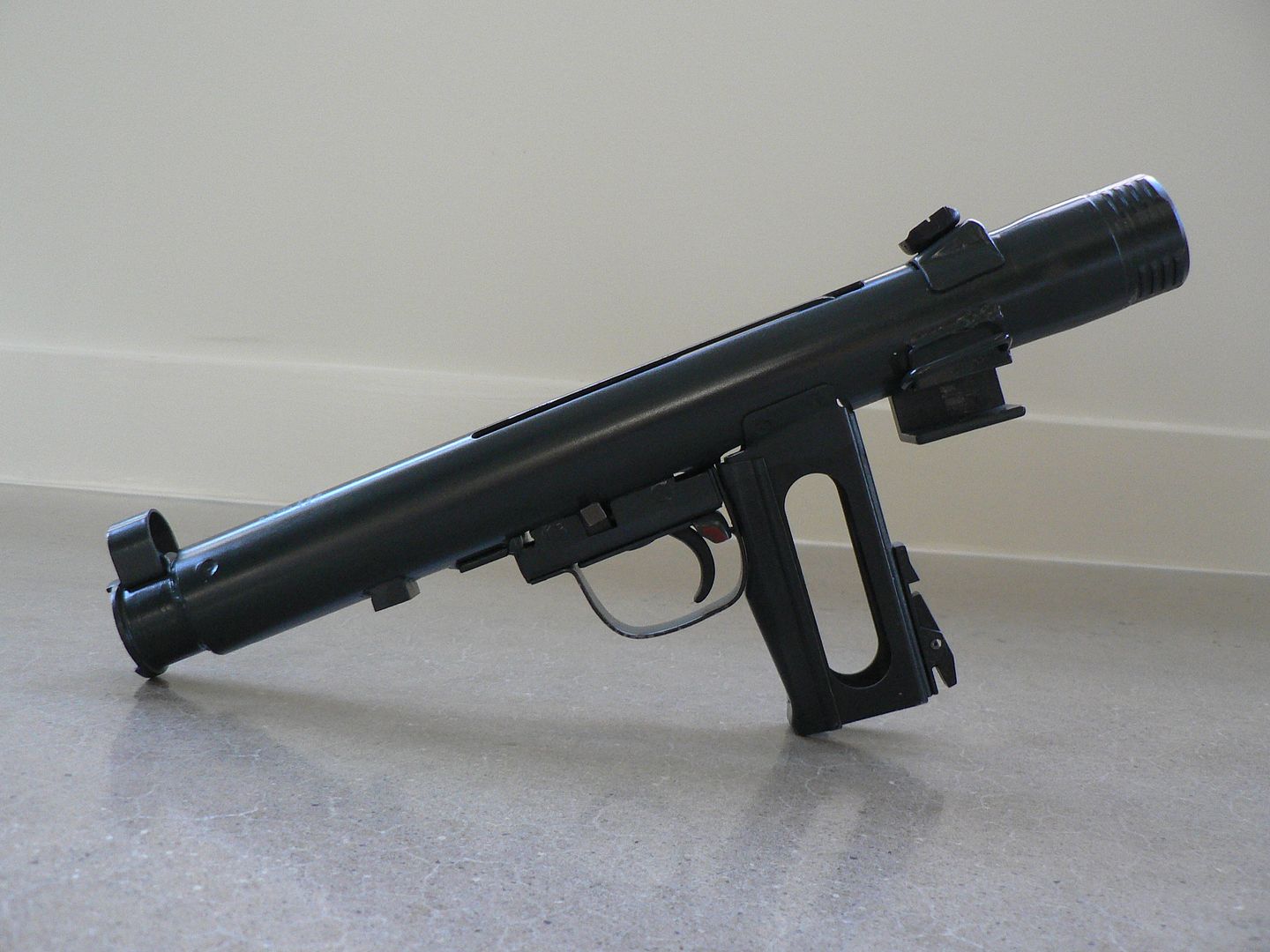
    I just picked this up this evening. It's technically not C&R but that's the crowd it would appeal to I think. The pictures aren't the best but I'll take better and more detailed ones when I get better light. I'll also post a range report when I get it to the range. I've wanted one of these little SMG's for as long as I can remember. While it's only a semi auto built from a parts kit, it's still neato. Greg Clark down at GunBuilds in Alabama built it using a TEC Tactical receiver and Re-Mil 16 barrel. While I've only ever handled one factory built Sa 26, the build quality of this one compares favorably to what I remember of the "real" one. Other than reliability, I don't expect much from this little clunker. While the trigger is decent, there is a fair amount of mass that flies forward when you pull it despite the fact that it fires from a closed bolt. When I show pictures of it taken apart, you'll understand why. Other things going against this being a paper target carbine are the fact that the sights are possibly worse than a STEN and the overall ergonomics are pretty terrible. Removing the guts, barrel and furniture revels just how minimalistic these things were built. It's essentially just a few bits of sheet metal cut out, bent into shape and spot welded together. Still, it was quite innovative for the time and it was just as well built as anybody else's stamped SMG design. Cheap was the idea from the beginning! And that's part of the fun as I am absolutely fascinated by stamped firearms. You don't buy one of these for any other reason than to just have one; if you're looking for practicality, you're missing the point! Anywho, here's the old clunker. As I said, I'll do a little write-up on it when I get time and good light for better pictures.

    Cast and stamped steel stock unfolded:


    The wood stocked version was called the Sa 24. The folding and wood stock are interchangeable.


    Stock folded to be used as a foregrip:


    Right side showing the magazine loader built into the forearm:

     
    Last edited:

    Combloc

    Stop Negassing me!!!!!
    Nov 10, 2010
    7,268
    In a House
    Lol....thanks. If it works......then it will be neat. For some reason, I'm a sucker for Czech stuff.
     

    Cruacious

    C&R Farmer
    Apr 29, 2015
    1,629
    Elkton
    Well, the Czech's DO make really cool stuff. I think it's neat myself, although I'd rather have a PPSc-43 (in full auto, mind) someday as my 7.62x25 toy. Well, a guy's gotta have dreams, right? ;)
     

    jjones88

    Active Member
    Apr 4, 2013
    568
    Sykesville
    I built one awhile back using the TEC Tactical Tube and his striker. It's a blast and an eye turner.

    I never got mine to work quite right with 9x19. The mag angle is slightly different and the bolt requires a mod to enlarge the ejection port.

    My guess is yours was modded by Greg to work with 9mm as it's easier to do the design that way and use it for 7.62x25 later.
     

    jjones88

    Active Member
    Apr 4, 2013
    568
    Sykesville
    Here's some shots of mine as it was being built. The trigger is an act of genius from the czechs....

    pt 1.jpg

    pt 2.jpg

    final 2.jpg

    final1.jpg
     

    Combloc

    Stop Negassing me!!!!!
    Nov 10, 2010
    7,268
    In a House
    Nice!

    Mine is marked "multi" for the caliber and I was told that it is 9mm ready. I didn't buy it from GunBuilds but from someone who did.
     

    Combloc

    Stop Negassing me!!!!!
    Nov 10, 2010
    7,268
    In a House
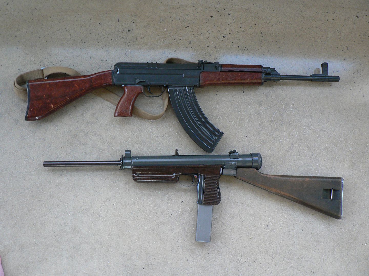
    I have not had this thing to the range yet but I had good light and some spare time so I tore into it. I ended taking way more pictures than I had originally intended so this is going to take a few posts to get it all up but the only way to get it done is to get it started! Forgotten Weapons has already done an excellent video on the Sa 26 so I won't be going into every single detail. Instead,what I am primarily doing here is showing how the semi auto version works (I call it the Sa 26s) and how well it was rebuilt. Additionally, I'll note some of what I consider ingenious construction and design details (both of the original SMG and Greg Clark's modifications). First, here it is with the wood stock attached and size compared to the rifle which made it obsolete, the VZ58:


    Even though the VZ58 officially replaced this and the VZ52/57, the Sa 26 must have still been in use for a long time afterwords as this one is stamped as being reworked in 1981.

    The dude I bought this from had GunBuilds supply it to him unpainted because he wanted to finish it himself using Duracoat's vz2000 paint while preserving as much of the original paint as possible. Thus, the end cap, stock, trigger group and magazine housing/pistol grip all show paint as applied by the Czechs. Although not a perfect match, it's quite good as shown here:


    In fact, in this picture, the color match looks dead on. But later we will see some pictures taken in different lighting conditions showing that they are not a perfect match. This is not a complaint as the original paint color varied over the years and you cannot expect a 100% match given this fact. Duracoat seems to have done a really good job if you ask me.


    To field strip this thing, it's as simple as making sure it's decocked, removing the magazine, pressing the button at the rear of the endcap, rotating the endcap until the interrupted threads disengage so that it can be removed and then pulling all the guts out the rear. Done.

    The magazine is removed by pushing the button at the bottom of the pistol grip and pulling the magazine out. It will not fall out on its own:


    Note the over-insertion tab spot welded on the back of the magazine in the picture above.


    Brefore going any further, lets take a quick look at the magazine. Because of the profile of the 7.62x25 cartridge and the fact that the magazine is a double stack, it has a distinctive triangular shape as can be seen here loking at the bottom view:


    Here is a top view:


    And a back view showing the notch for the magazine catch and the witness hole. Why it is there is beyond me. It 's a 32 round magazine but the rounds show in the hole beginning at number 14? Beats me.


    They must have made loads and loads of magazines for these things because this one was made in 1950 and was absolutely brand new. I know this because after just one time being inserted and removed from the magazine well it showed wear marks where there were absolutely none before. That means it had never been used in 67 years! I have a bunch of others and they are either new or as new too. Some have dates and some have only the crossed swords property mark.


    Here is the endcap removed showing the interrupted threads and the push button that holds it in place. Notice how there are two pins on the push button plate that engage with the inside of the end cap to keep it from rotating. They form a very positive lock when engaged. Given that your eye is right there when you are aiming, they need to!


    Notice that there is no particular position the endcap needs to be in when assembling it onto the receive tube. You only need to make sure that any of the dished areas on the cap line up with the threads on the tube then push and rotate either direction until you hear a "click" letting you know that it's locked in place. Also notice that the push button plate has a tab which indexes with the receiver tube. This keeps it from rotating resulting disastrous results to the user's face!


    Here we see the bolt, recoil spring, striker spring......everything being withdrawn out the rear of the receiver:


    Everything comes out as a unit on both the open bolt and closed bolt designs. On the vast majority of firearm designs, you need to remove a separate recoil spring and charging handle. But those crafty Czechs figured out a way around having to remove those extra bits and to be potentially lost in the field. The recoil spring is attached to the bolt and we'll look at that later. Lots of designs do that. But it's the charging handle design that's really ingenious here. You see, it's spring loaded and is always trying to pull itself into the bolt but it can't when assembled because the notch in the receiver it thinner than the width of the handle. Let's look closer.

    Here we see the charging handle pull almost to the rear of the slot cut unto the receiver:


    Notice that the rear of the slot becomes a wider opening and has a small ramp at the front of the opening leading towards the inside of the receiver. When the firearm is assembled, the charging handle can never reach this opening. But during disassembly, the bolt can be drawn to the rear far enough that the charging handle reaches this opening and the spring in the bolt can now begin to pull the charging handle inside. Here, it is seen part way retracted into the bolt:


    And finally, fully retracted allowing the bolt to be fully withdrawn from the receiver:


    The ramp comes into play during reassembly. You see, the charging handle has a cutout underneath it at the front that hits this ramp and, as the bolt is pushed forward, it follows this ramp up and out of the bolt back into the deployed position. Pure genius!


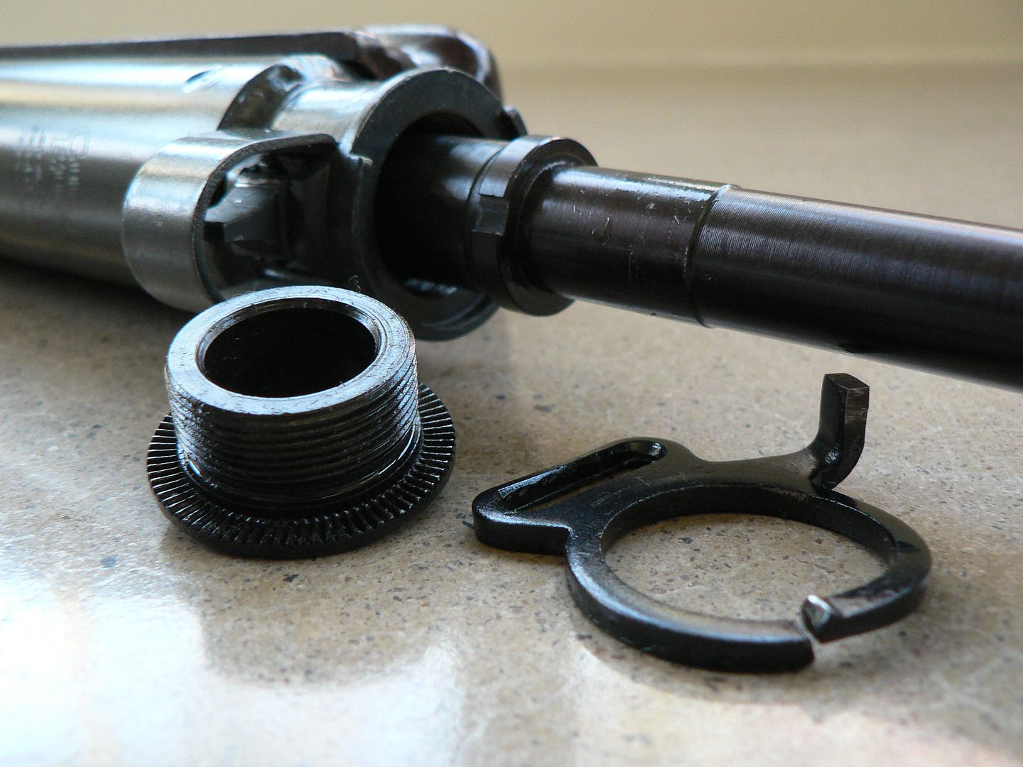
    Moving to the front, we will remove the barrel. It is held in place by a nut that screws into the trunnion and is held in place by a ratchet mechanism:


    There are two lugs on the barrel nut that engage with slots cut into the front of the bolt assembly allowing it to be used as a wrench for disassembly. We can see one lug in the above picture. The other is 180 degrees round the other side and is hidden by the barrel in the picture.


    Here we see the nut removed while the barrel loose partly removed showing the index slot cut into it for proper alignment in the receiver:


    The index slot faces "up" when assembled and engages with a pin welded inside the front trunnion which is itself welded into the front of the receiver tube. Originally, the receiver tube would have been crimped and welded in place similar to an MP40 but Gunbuilds skips the crimping part. This is fine IF the trunnion is perfectly aligned. Part of the reason is has to be perfectly aligned is because the front sight is attached to the trunnion and you don't want canted sights. The other reason is that the barrel indexing pin is part of the trunnion and absolutely MUST be in the proper position. Otherwise, the extractor slot at the rear of the barrel will not line up with the extractor in the bolt causing major reliability problems. In a mass production factory environment circa 1952, these things are non-issues because everything is semi-automated and alignment is built into the process. In a small workshop, the only way to prevent problems is attention to detail and well thought out jigs. GunBuilds seems to have a good reputation for these things. I'm going to find out if that reputation is deserved soon.
    Also shown in the picture is the back of the barrel nut showing the ratcheting cuts and the sling swivel which doubles as the fixing point for the stock when folded and triples as the ratchet pawl. Notice that these is a small ridge running most of the circumference of the front trunnion. The missing part serves to keep the sling swivel from rotating. Also, making the sling swivel the ratcheting pawl was quite smart because, should the pawl be worn down through use, it's a simple thing to replace a small stamped part. Had the pawl been built into the trunnion the design would very likely have been much more complicated. Any time you can design a cheap and easily replaced part that serves multiple functions, you are improving the end product.


    The last picture for this post shows the clunker field stripped. The stock has been removed for illustrative purposes:


    I was careful to place the barrel and bolt relative to how they would sit in the receiver when assembled. I also show the barrel just a bit longer than it would be if it were original length. By today's standards, this is an obsolete design. In fact, some of you younger folks might go so far as to call it junk. BUT, in the 1940's when it was originally designed, the Sa 26 was outstandingly innovative. Nobody had yet mass produced a firearm incorporating the magazine behind the trigger in the pistol grip and a bolt that surrounded the barrel allowing a longer barrel in a more compact design. It was essentially a bullpup SMG and it was revolutionary. Things like this are why I am so fascinated by Czech firearms. Like the Swiss, they largely ignored what others were doing and went their own way.......and it worked! At the same time, it was extremely simple to manufacture and cost effective. Compared to the UZI which followed and borrowed heavily from it, the Sa 26 is somewhat inefficient and clumsy but without the Sa 26, there very well may not have ever been an UZI. It is the original.....it is proof of a concept and it is the inspiration for much of what followed. Yet, like many revolutionary designs, it is largely forgotten because it was surpassed by what followed. That is almost always the way with such things.

    In the next post, we'll begin looking at the semi auto bolt and what Greg Clark of GunBuilds did to make it happen. See you in a bit!
     
    Last edited:

    Combloc

    Stop Negassing me!!!!!
    Nov 10, 2010
    7,268
    In a House
    Alrighty....picking up where I let off, let's look at the semi auto bolt. Greg Clark uses an original bolt and modifies it from open bolt operation with a fixed firing pin into closed bolt operation with a striker. He also modifies the receiver so that an unmodified bolt cannot be inserted. Let's look at some pictures!

    First is the left side and front is to the left of the picture:


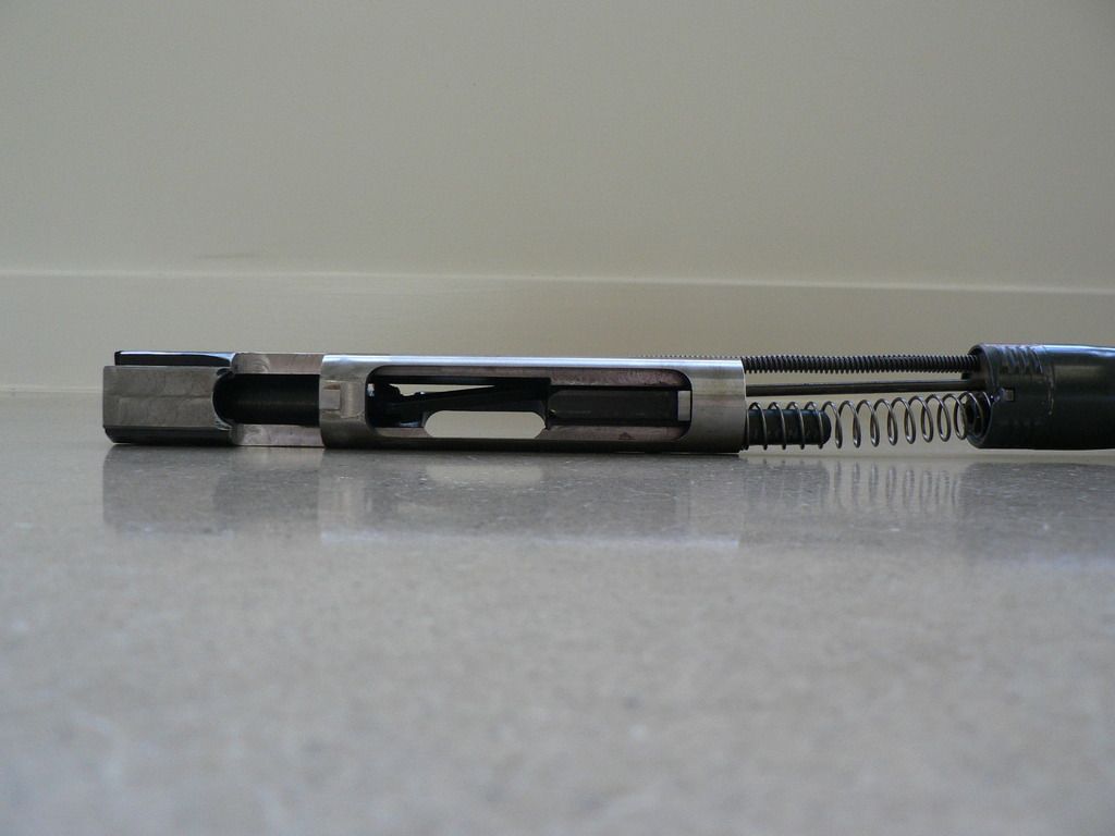
    Notice that the entire assembly (bolt and striker) is basically two parts that can move independently of each other. The upper part is an original modified bolt and the lower part is a new made striker. The smaller diameter tightly coiled spring is the original recoil spring. The larger diameter loosely coiled spring is the newly added striker spring. When you pull the charging handle fully to the rear, both parts slide backwards in the receiver, clearing the magazine and allowing a round to move up into position ready to feed. When you release the charging handle, the upper part of the assembly (the original modified bolt) is driven by the recoil spring and runs fully forward, stripping a round from the magazine and seating it in the chamber, ready to fire. Meanwhile, the lower part of the assembly (the new made striker) remains to the rear, held in place by the sear in the semi-auto only trigger pack. The striker spring is compressed, ready to run the striker home when the trigger is pulled, lowering the sear. The picture above shows the bolt and striker assembly fully forward at the instant of firing. The picture below shows everything in the cocked and ready to fire position:


    Note that the striker spring has been removed in the above picture in order to allow the illustration. It would be partially compressed if it was shown.


    Here is the bottom of the bolt/striker assembly:


    To the right of the picture, the rear end of the receiver can be seen. This was necessary in order to hold everything in place to take the picture. Otherwise it would tend to roll. Again, front is to the left. Originally, the sear would catch on a lug machined into the bottom front of the bolt. That has been removed for the conversion to semi-auto only. Now the sear engages with the extreme front of the striker.


    Top of bolt/striker assembly:


    The ejection window can clearly be seen. The notch running the entire length of the assembly allows clearance for the little ramp at the rear of the receiver charging slot. We looked at this ramp and how it guides the charging handle during reassembly in the last post.


    Right side of the bolt/striker assembly. Rear is now to the left of the picture:


    This picture show how well machined the bolt and striker are to each other. It is very smooth in operation with no grinding or discernable friction when you slide the parts against each other:


    Here, we see the striker spring removed:
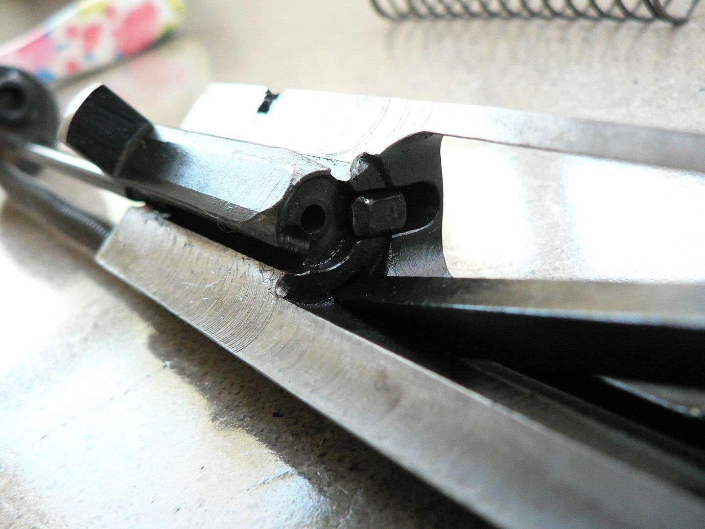


    The recoil spring is seen at the top of the picture. The rod next to the recoil spring is the ejector rod. It is fixed to the back plate (which also serves as the disassembly push button). As the bolt slides to the rear during recoil, the ejector rod emerges from the breech block face, striking the rear of the spent casing and throwing it out the ejection port. GunBuilds has welded a plain old threaded nut to the back place to capture one end of the striker spring. It's not the most elegant solution but it works! The black rubber thing sticking out the back of the bolt has also been added by GunBuilds. It captures the other end of the striker spring and doubles as a sort of buffer I guess. It's nothing more than a piece of fuel line slipped over a bit of steel rod welded to the striker:


    At least it'll be easy to replace if it ever degrades.


    This is the striker removed from the bolt:


    It is pretty heavy. In fact, it's so heavy that you can feel the entire rifle jump slightly when it slides forward to fire a round similar to what would happen if the rifle was actually fired from an open bolt. The long firing pin can clearly be seen.


    A nice design feature of the striker is slot cut into it allowing removal from the bolt without having to first remove the recoil spring and ejector assembly:


    Normally, there is no need to remove the recoil spring/ejector assembly from the bolt. It is held captive at the front of the bolt and can be a little fidgety to replace once removed. But, should you wish to, you just compress the recoil spring a bit and pull the guide rod out of the cutout in the bolt. Then you simply slide the recoil spring/ejector assembly to the rear and out of the bolt:


    Here is a view of the recoil spring and rod held captive at the front of the bolt:


    The two notches cut into the front of the bolt engage the lugs on the barrel nut for removal during field strip. With the original length barrel, the bolt just slides over the barrel until both notches engage both barrel nut lugs. With a 16" barrel this is not possible because the length of barrel protruding from the receiver is such that the breech block face would hit the muzzle long before the front of the bolt would contact the barrel nut. Not to worry. Just place the bolt beside the barrel and use one notch on the bolt to engage one lug on the barrel nut. The fit is tight enough that it works just fine using it this way without screwing anything up. You aren't going gorilla on it after all. You just want to snug it up enough that it won't loosen in use. Easy peezy.


    There is more coming but it's getting late so I'm off to bed. If you aren't bored yet, stay tuned for more schtuff.
     

    jjones88

    Active Member
    Apr 4, 2013
    568
    Sykesville
    That's curious, your striker is different at the front then mine. Yours has a lip and mine does not..

    Your photography exceeds mine, but you should show how you tighten the barrel nut with the bolt. That is czech ingenuity right there.
     

    Combloc

    Stop Negassing me!!!!!
    Nov 10, 2010
    7,268
    In a House
    Thanks guys!

    Hi!! I'm picking up where I left off. First, we'll finish up looking at the bolt modifications and a few other miscellaneous pictures of the internals. Then we'll look at just how simple and inexpensively made the shell of the Sa 26 really is. Lastly, we'll finish up with a look at the bakelite bits. So let's get to it.

    Here is the rear of the bolt with the striker removed:


    You can see how the recoil spring and ejector rod run into the rear of the bolt. Having the ejector made as part of the recoil assembly and not mounted to the receiver is good design. It's easily replaced with no tool in the field and it also simplified the entire design. It's also so heavily built that it's unlikely to ever fail.


    Here we have removed the recoil spring/ejector assembly:
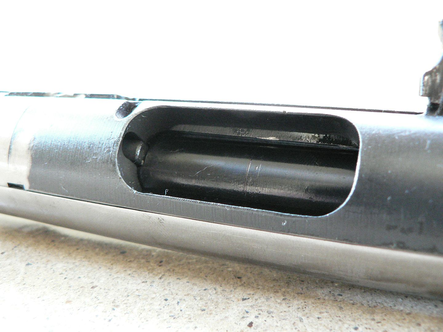


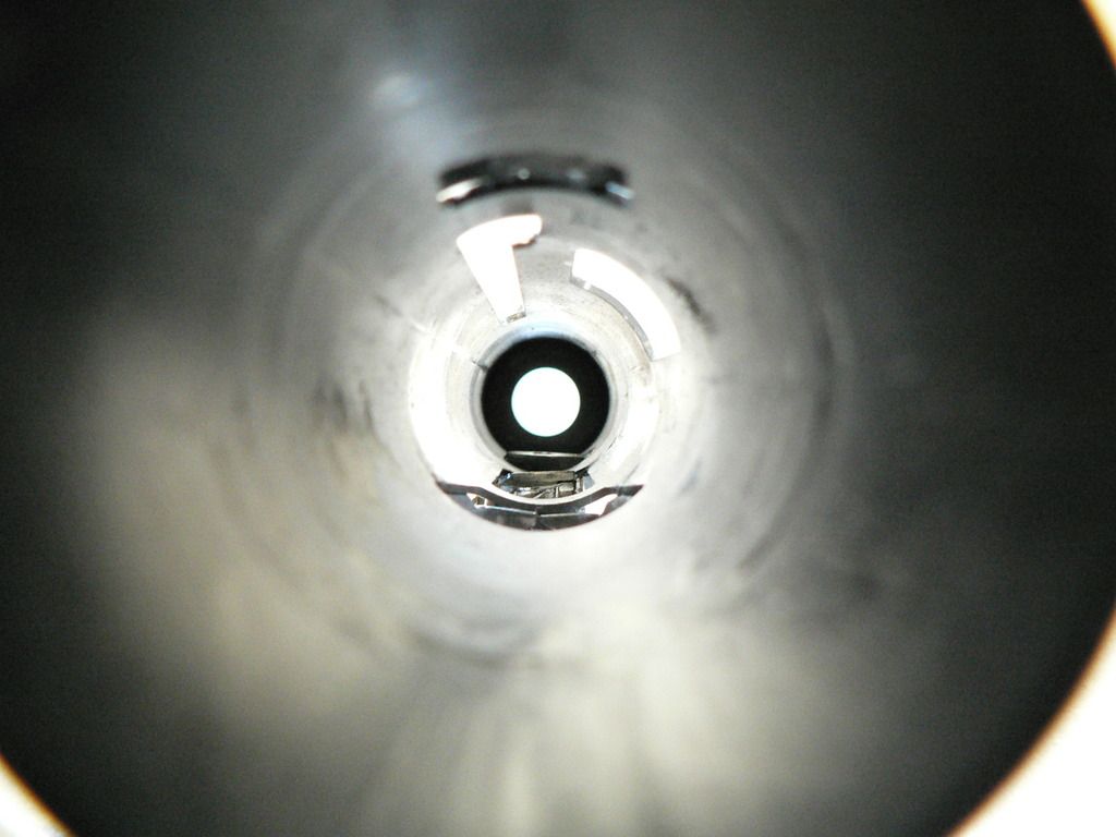
    Notice how the recoil rod and spring are recessed into the side of the bolt making the design more compact and while also allowing the main receiver body to be constructed of simple round tubing. The smaller hole in the center of the bolt has been added by GunBuilds for the firing pin to pass through. Remember, this originally had a fixed firing pin machined into the bolt face. At the two o'clock position, you can see the rear of the extractor.


    Here is the bolt face with the striker removed showing the new firing pin hole:


    The angled bar seeming to emerge from the bolt face and exiting the right side of the picture is the charging handle. As stated earlier, it is spring loaded and will pull itself into the bolt when the bolt is removed from the receiver.


    Striker in place and fully forward showing how far the firing pin protrudes:


    Here, we have slid the barrel into the bolt and we are looking at it through the ejection port in the bolt:


    Notice how thick the walls are on the bolt. It is very heavy and would probably make a good hammer were it not for the fact that it is round.


    In this view, we are looking at the bottom of the bolt with the barrel in place. Front is to the right:


    It shows just how much longer the barrel can be when using this design.


    Here is a view into the rear of the receiver with the bolt/striker assembly and barrel removed:


    The first hole we come to along the bottom is the magazine well. In front of that is the hole where the sear enters. The sear is fully raised. At the front of the receiver is the block which prevents insertion of a full auto bolt. At first thought, you would think that all you need to do to convert this back into an open bolt design is to mill a notch into the front of the bolt. You would be wrong. The block sits right where the sear lug on the bolt was. What you would end up with is an illegal SMG that would run itself dry when you cocked it because you just bypassed the trigger mechanism. In short, DON'T DO IT.


    A slightly different angle showing the charging handle slot and ejection port at the top of the receiver:


    The hole to the rear of the charging handle slot is where the rear sight fits.


    One last picture for this post looking through the ejection port:


    The magazine and barrel are in place and the bolt has been removed. Given the fact that the rounds feed almost straight into the chamber, I am expecting no feeding issues.
     

    Combloc

    Stop Negassing me!!!!!
    Nov 10, 2010
    7,268
    In a House
    So, we are finished with the insides. Now lets look at the construction of the receiver and GunBuilds reassembly work. When you initially pick up the Sa 26, two things strike you immediately. First is just how heavy it is. I haven't weighed mine but, according to he internet, this thing weighs over 7 pounds empty. That's about a pound heavier than the VZ 58 and just a little tiny bit heavier than a standard AKM. That's kinda crazy for a little SMG when you think about it. The other thing that grabs your attention is how bad the ergonomics are. The pistol grip is too short and your little finger rests on the magazine. The safety is hard to manipulate. The folding stock is uncomfortable and the wood stock is only marginally better. The sights are beyond horrid. I could probably come up with more but you get the point. Despite these things, it's really, REALLY cool looking!! It's so cool looking that Sean Connery used one in the opening scene of Never Say Never Again. But I digress.....
    We always see pictures of the Sa 26 as a complete firearm. When seen like that, yes it looks like a grease gun to be used underneath your jeep but it also looks kinda' complicated. It's only when it's stripped down to the basic frame that we see just how minimalistic the design really is.

    Here is the left side:


    And the right side:


    It's really nothing more than a tube with a machined trunnion welded into one end and some machine work done to the other end. Tack welded to that is a magazine housing and a few other bits like rear sight, stock fitment point and forearm mounting block. Add in a pinned on trigger box and, voila, you have a heavy non-ergonomic SMG! When stripped down like this, it really doesn't weigh much. It's the barrel and massive bolt that really puts on the pounds.


    Here are close-ups of the left and right sides of the trigger box:


    Originally, this would have been held on with two pins so as to be removable for repair. However, it is now welded into place because it has been modified to allow fimi auto operation only. Were it still pinned, it would make it that much easier to convert back to full auto. I am assuming that welding this part on was a requirement for ATF approval. You can see the spot welds where the pins would have been fitted. The safety has a dab of red paint on it to remind you which position it is in. That's how it left the factory. Especially noticeable on the left side is where the original paint and Duracoat vsz2000 meet.


    Next are a few shots showing some of the welding Greg Clark did.

    Rear sight and stock fitment point:


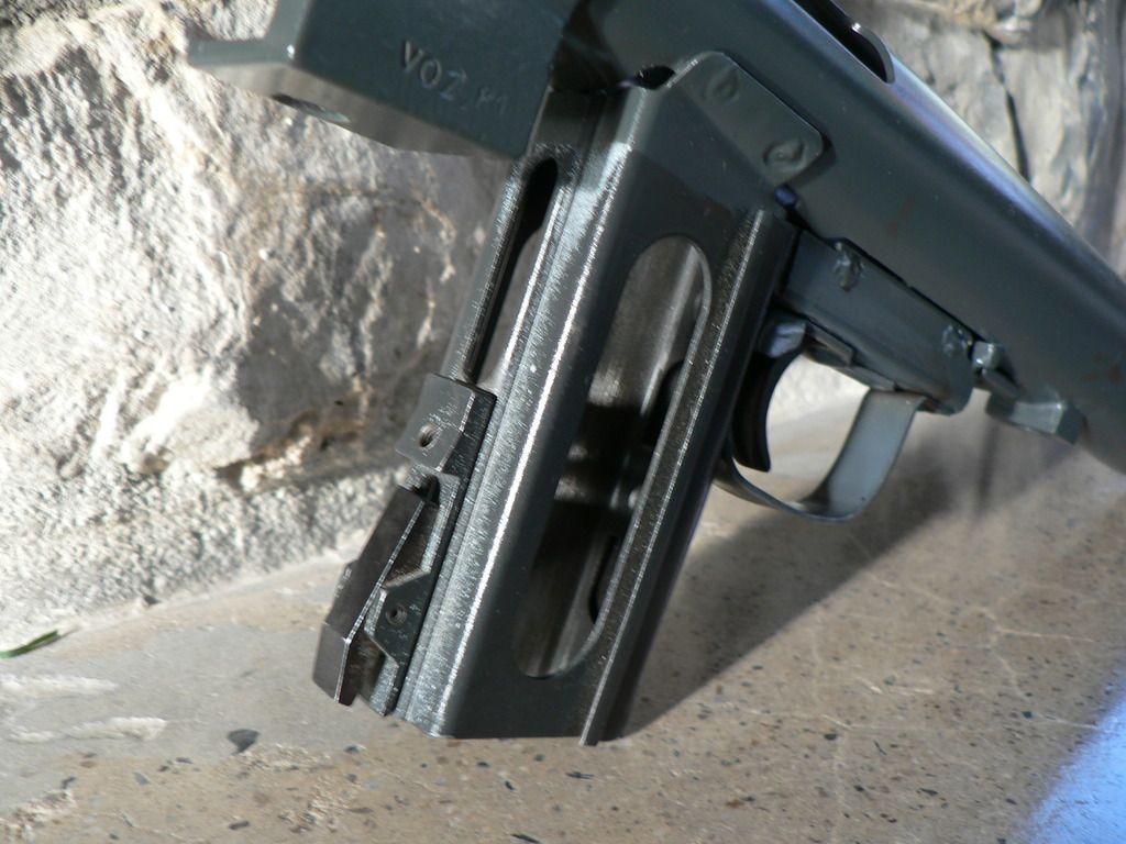
    Notice the "VOZ 81" stamp. That means that whatever SMG this part came from had been arsenal refurbished in 1981. This same mark is used on all Czech firearms during the communist era. Also visible on the rear sight is a "2" denoting 200 meters.


    Left side of magazine well again showing the dividing line between original paint and Duracoat:


    Front trunnion:


    While all of his welding seems to be plenty strong, it's obvious he does his best work in places that will be seen when assembled. That's not a knock, just an observation. I've seen this same thing on factory produced firearms as well. His work on the front trunnion is as good as on my HK's.
     

    Combloc

    Stop Negassing me!!!!!
    Nov 10, 2010
    7,268
    In a House
    I'm in the home stretch! This is the last post.

    I want to take a quick look at the magazine well because it shows the simple construction design philosophy embodied in this firearm.

    Here are two pictures of it:


    The main boy of it is made of two stamped parts. one part is folded into a box with the seam facing forward. To this is spot welded the front strap. It is wider than the main box and folded along the sides creating a lip to slide the front of the bakelite grips into. Spot welded to the rear of the box is the machined magazine catch comprised of the base, catch, spring and axle pin. That's it. Five parts make up the entire magazine well and magazine catch. Then this entire assembly is the spot welded to the receiver. It's like origami!

    Here we see how the grip panels are held in place:


    Again we see the slot for holding the front of the left grip panel. A stamped plate is fitted into a recessed area molded into the rear of the panels and held in place by a screw that fits into a tapped hole in the magazine catch base.


    The forearm is a big heavy chunk of bakelite held in place by one screw up through the bottom that affixes to a lug welded on the bottom of the receiver:


    The screw seen on the left side is one of two that attaches the magazine loader to the forearm.

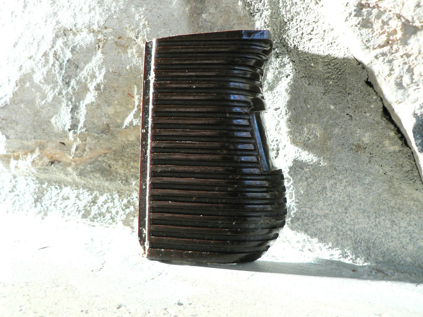
    Both sides of a grip panel:


    Unlike the VZ58 which uses wood chips mixed in with the bakelite resin for strength, the Sa 26 furniture uses what appears to be threads mixed in. Although it is heave, I absolutely LOVE bakelite. It looks better than modern polymer and it smells neat two when you rub it with your finger. It's just a reminder of the way thing used to be done.


    We'll finish up with a size comparison between the Sa 26s and a Vz61 SBR:


    The Vz61 has much more machining than the Sa26 but overall, I don't think there is a real difference in build quality. It is important to note that the Vz61 was not designed as a replacement for the Sa 26. The Vz58 did that. But, both are Czech and both were in service at the same time for at least a short while. So, they don't mind being seen together.
    Well, that's it. Now you know what to expect if you call up Greg Clark at GunBuilds and ask him about building a Sa 26s for you. My serial number is a single digit so I assume that there aren't loads of these floating around out there. If it shoots as good as it looks, I'll give it two thumbs up. We'll find out soon because I will have a little free time on the horizon and it's off to the range for a test. I'll update this thread at that time. If you made it through all of this without gouging your eyes out, thanks for your time and I hope you found it worth while. If I'm extremely lucky, I even taught you something you didn't already know! See you soon!
     
    Jul 1, 2012
    5,741
    Man, I thoroughly enjoyed this thread.
    Great walk-thru of the gun, super pics with all the details and what-not, thanks!
    and fur sure a LOT that I didn't know (but that bar is pretty low).
     

    Combloc

    Stop Negassing me!!!!!
    Nov 10, 2010
    7,268
    In a House
    Lol. The bar is even lower for me....I guarantee it! Thanks for the remarks and I'm glad you enjoyed it! I always laugh at myself after I've posted and I go back some time later to read it again. It's always full of spelling and grammatical errors. Sometimes I go back and edit them and sometimes I don't. I had a few e-books in the works but they remain unfinished because I got sucked into the new house. Eventually I want to finish them and I promise that they will be better written. But then I will go back and read them later only to notice screw ups I missed.........it never ends.
     

    Users who are viewing this thread

    Latest posts

    Forum statistics

    Threads
    275,640
    Messages
    7,289,442
    Members
    33,491
    Latest member
    Wolfloc22

    Latest threads

    Top Bottom