Combloc
Stop Negassing me!!!!!
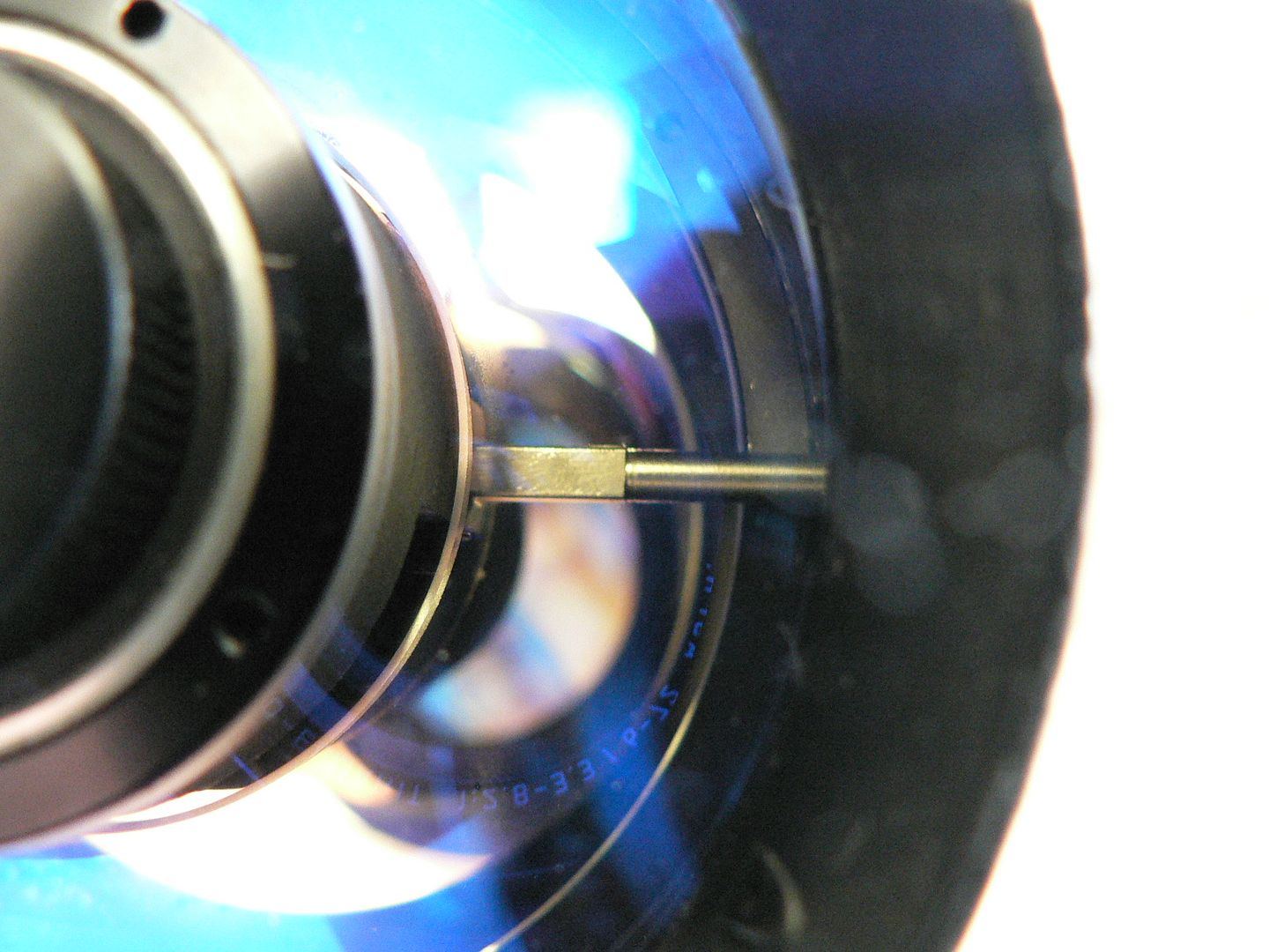
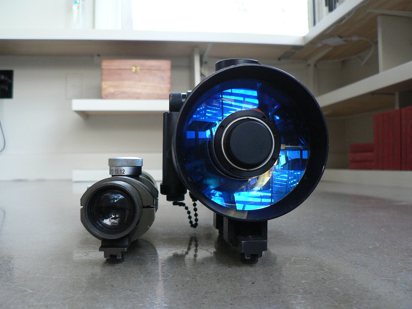
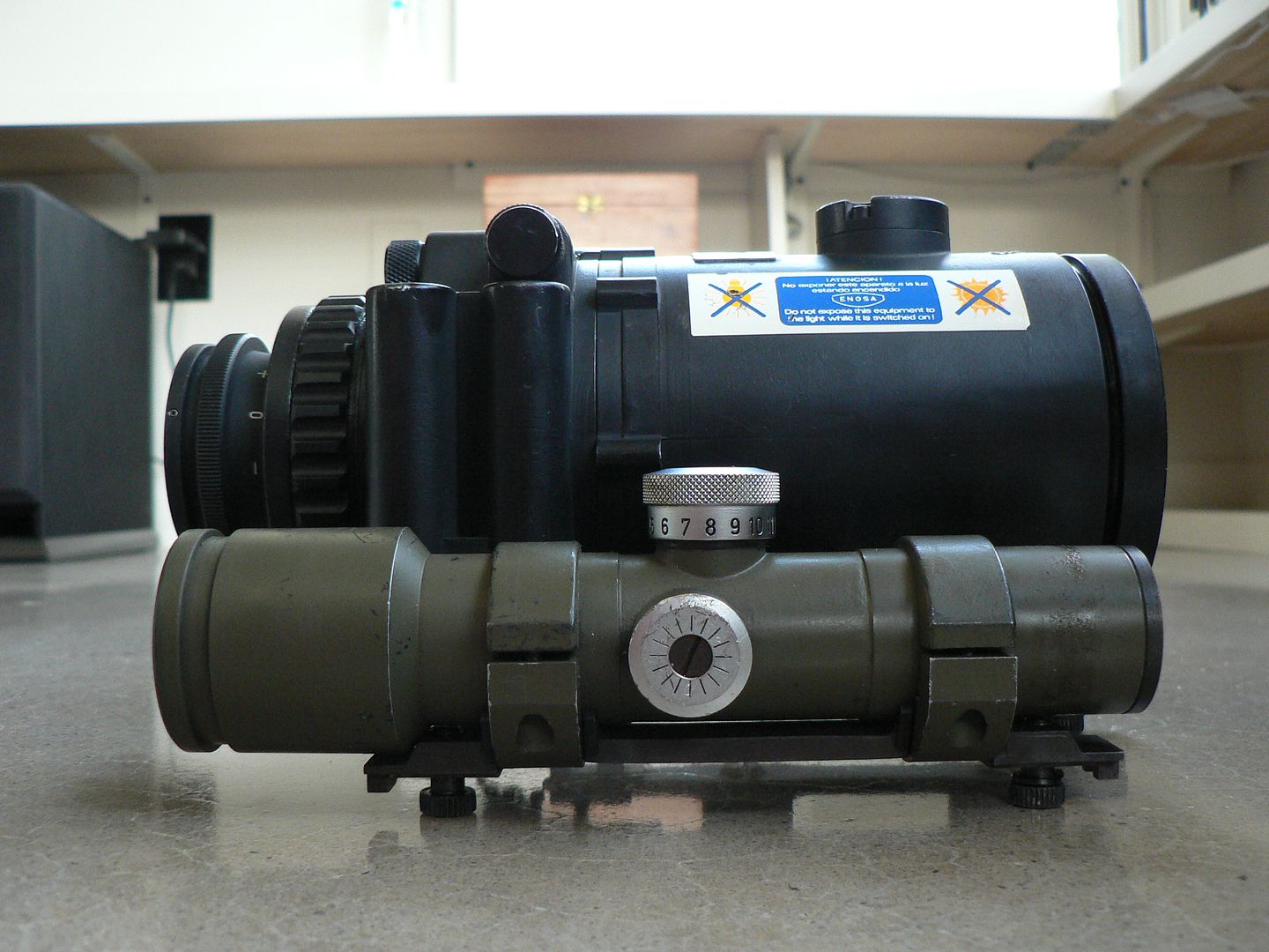
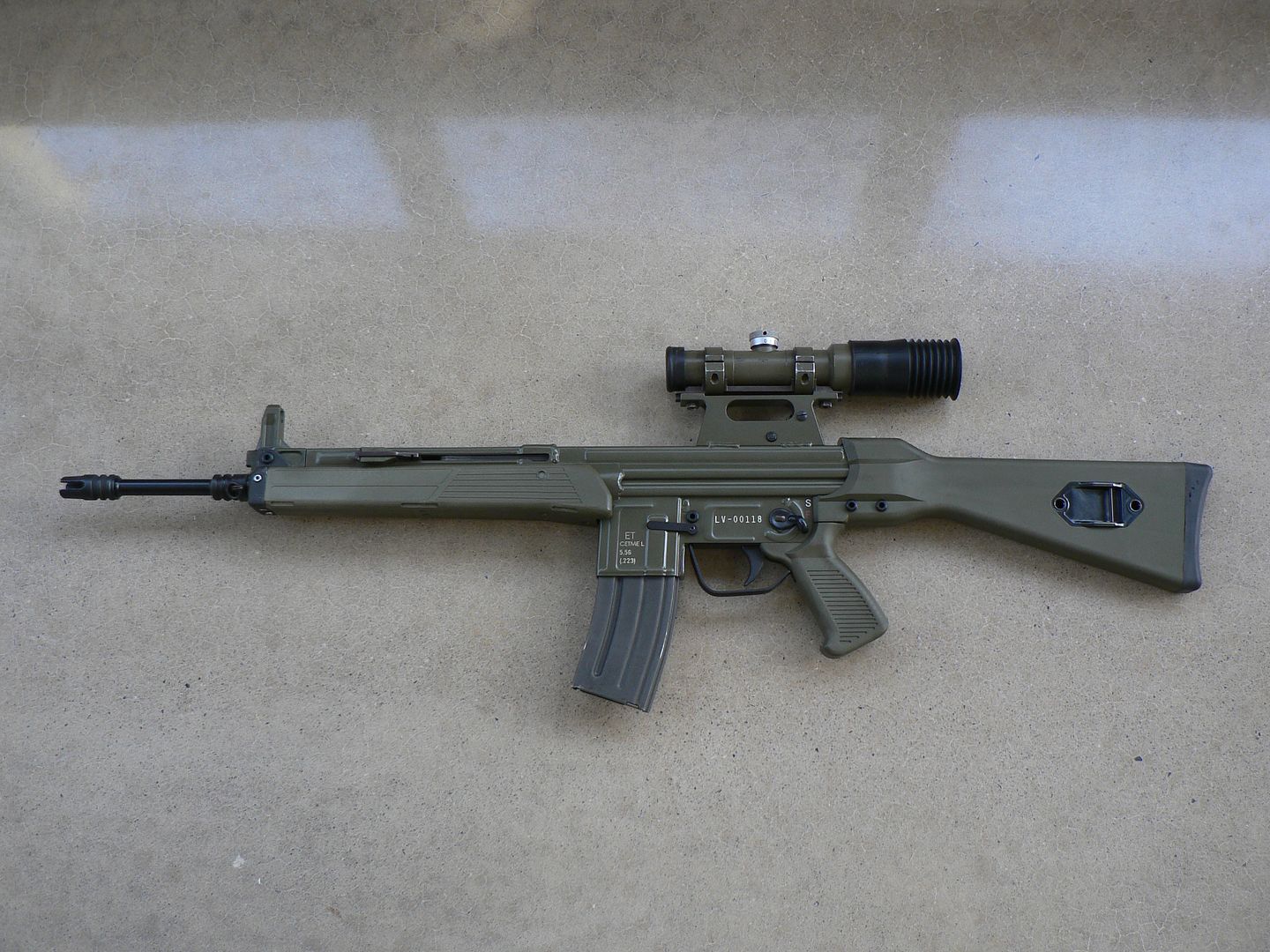
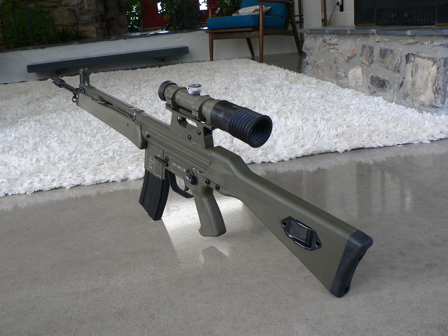
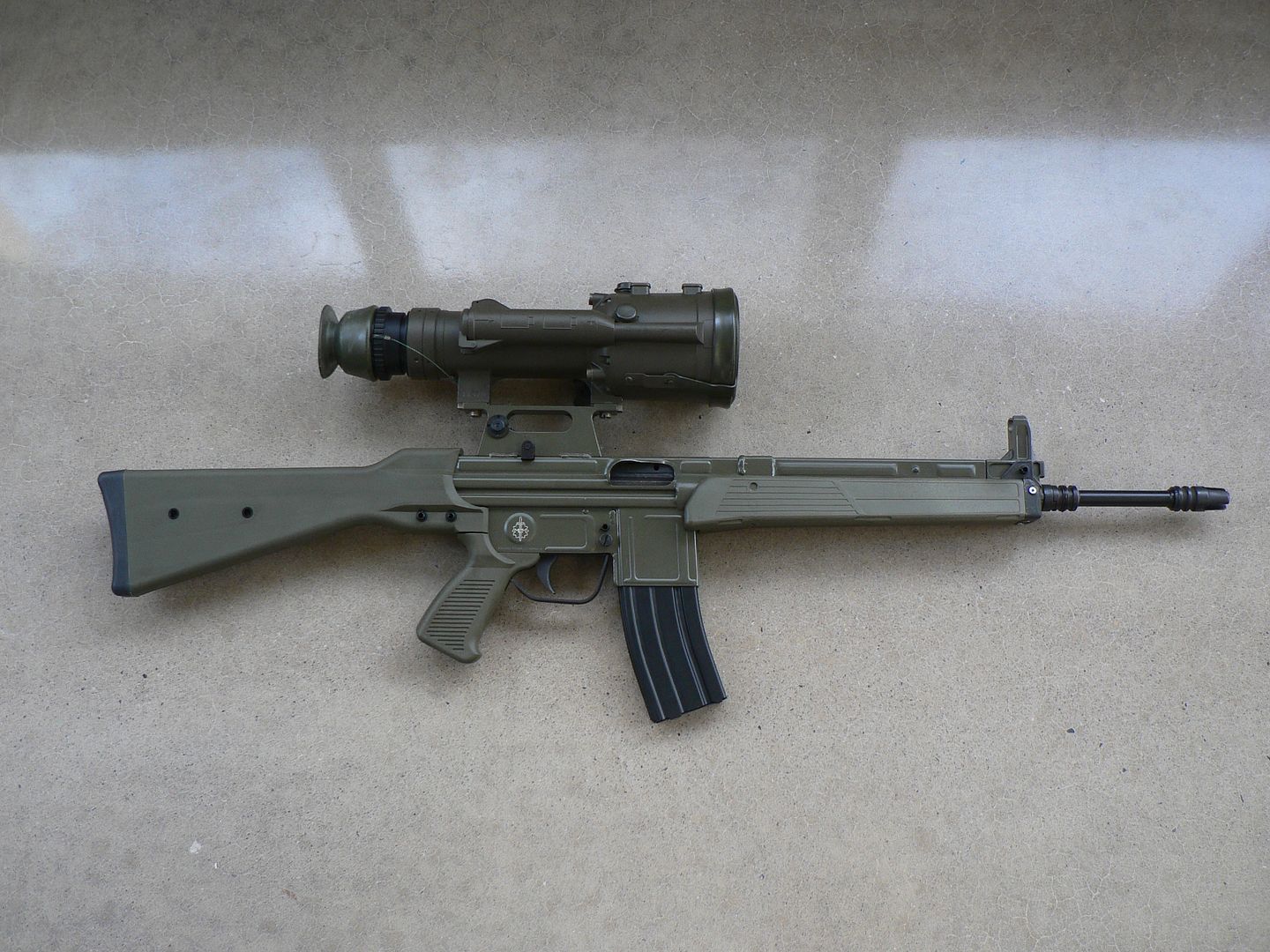
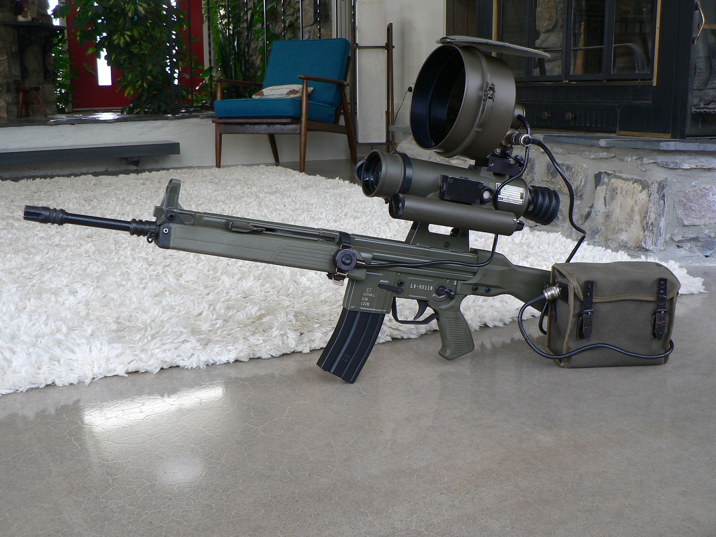
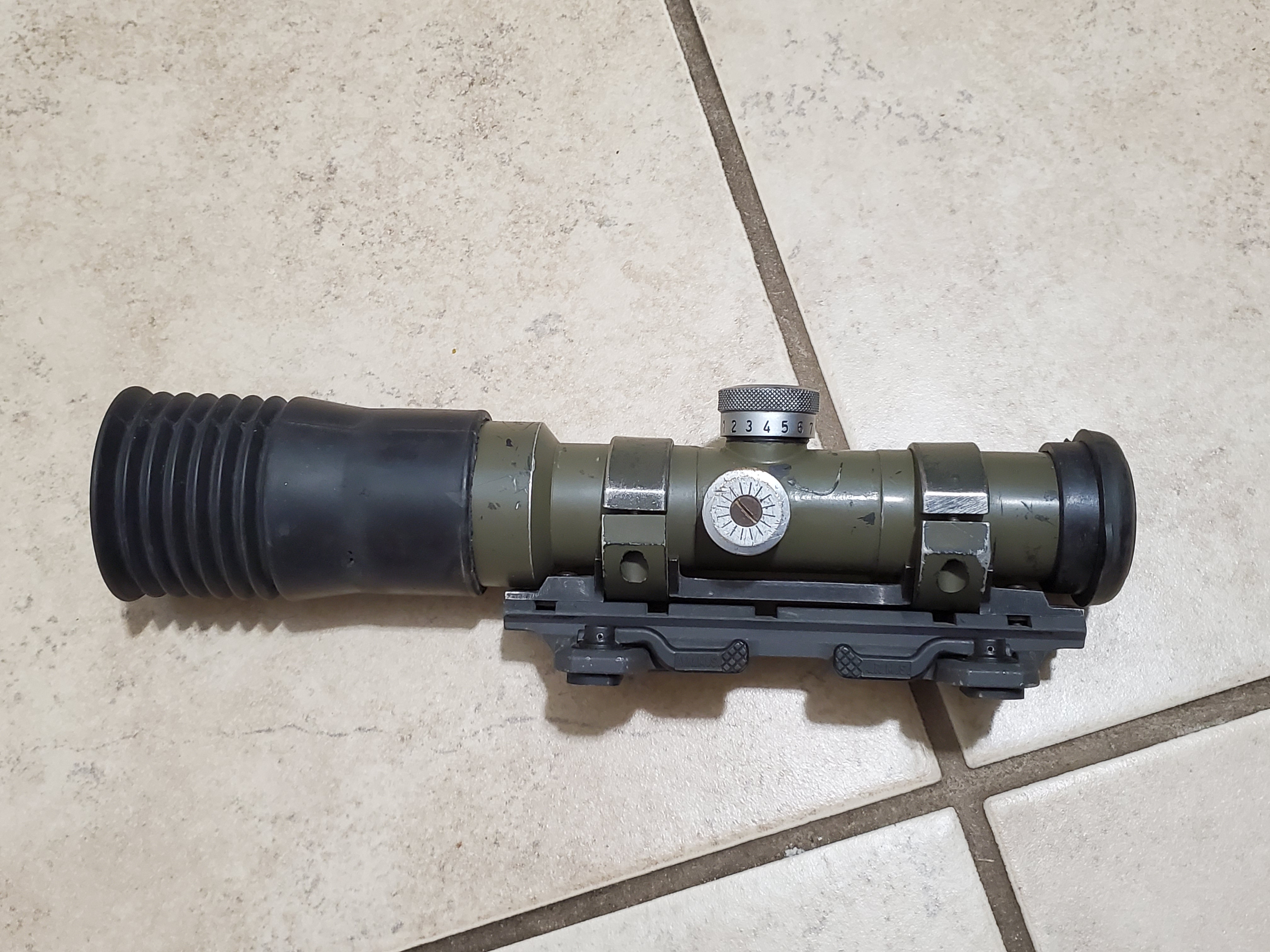
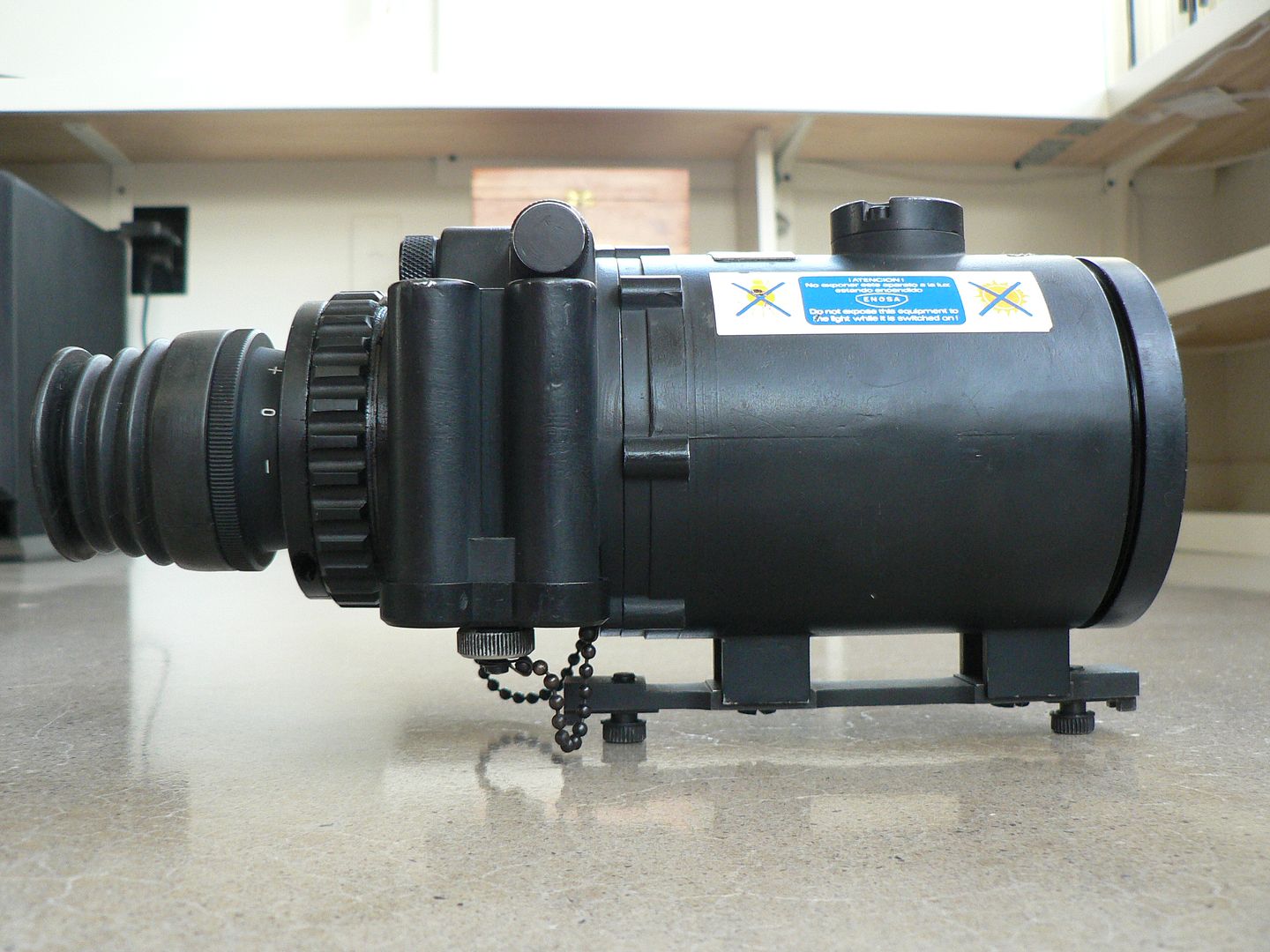
Left side of the Gen 2 VNP-009 scope with front towards the left of frame:
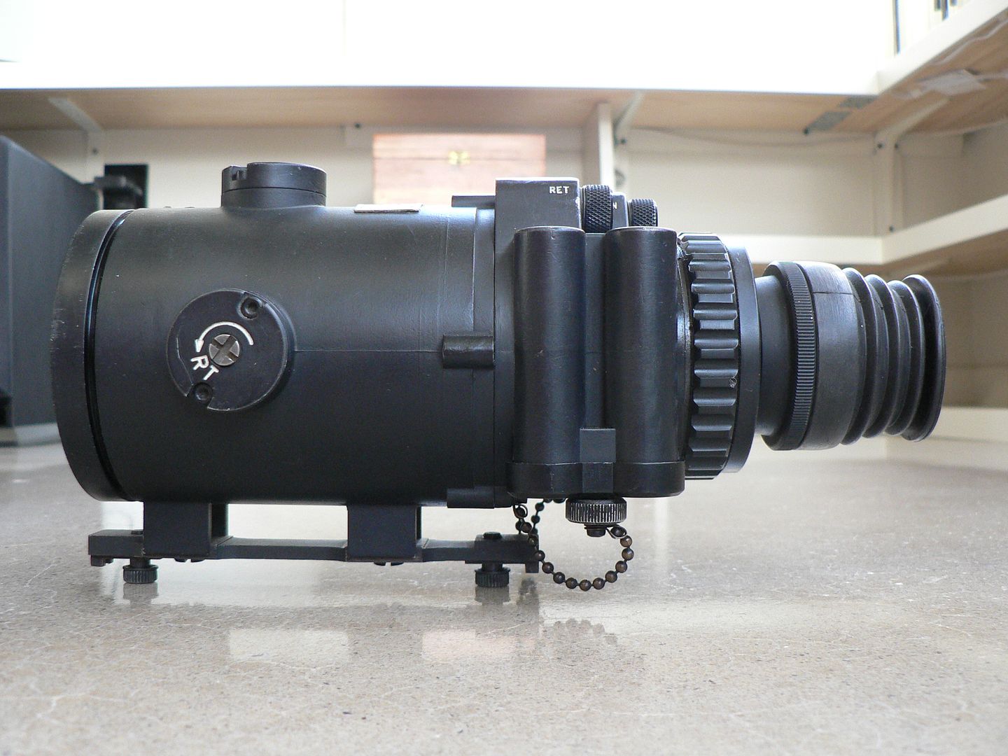
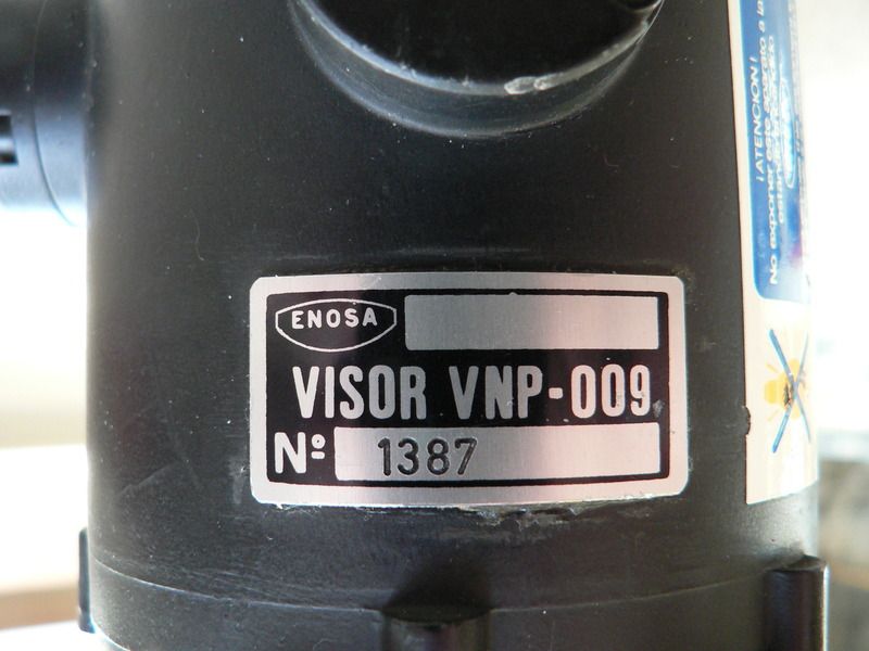
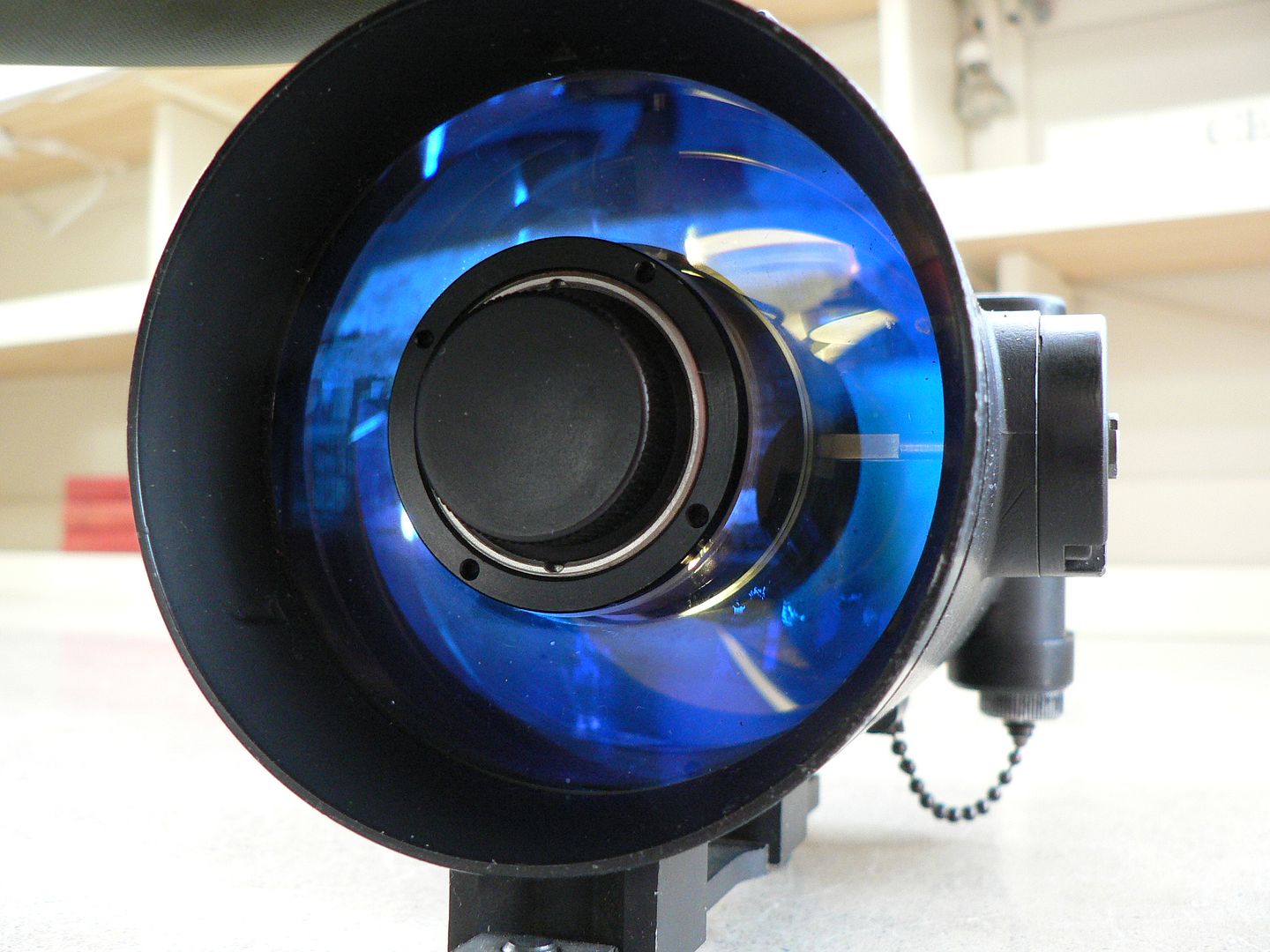
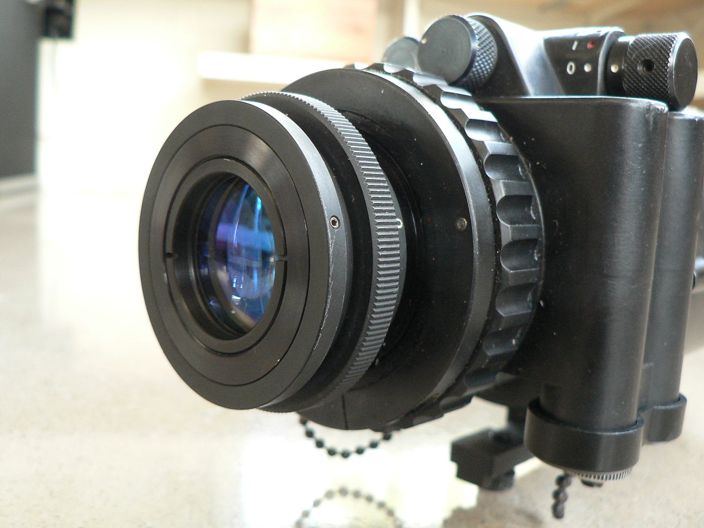
You read that right, this is a Gen2 unit and I believe it is most likely made in the Unites States or, at the very least, of US and British components. The entire front lens block is essentially identical to an AN/PVS-4 and all controls are in English. The feel and operation of it is also smoother and, for lack of a better term, more sophisticated than the Model F scope. The Quality of the image is also as good as US Gen 2 equipment of the era. The round lug with marked with an arrow and "RT" (the abbreviation for "RIGHT") is the windage adjustment and it clicks as you turn it with a coin or similar. Each click counterclockwise moves the point of impact 2.5cm to the right at 100m. The Spanish word for "Right" is "Dereche". Farther back, the two vertical tubes are the left side battery compartment which holds two AA batteries.
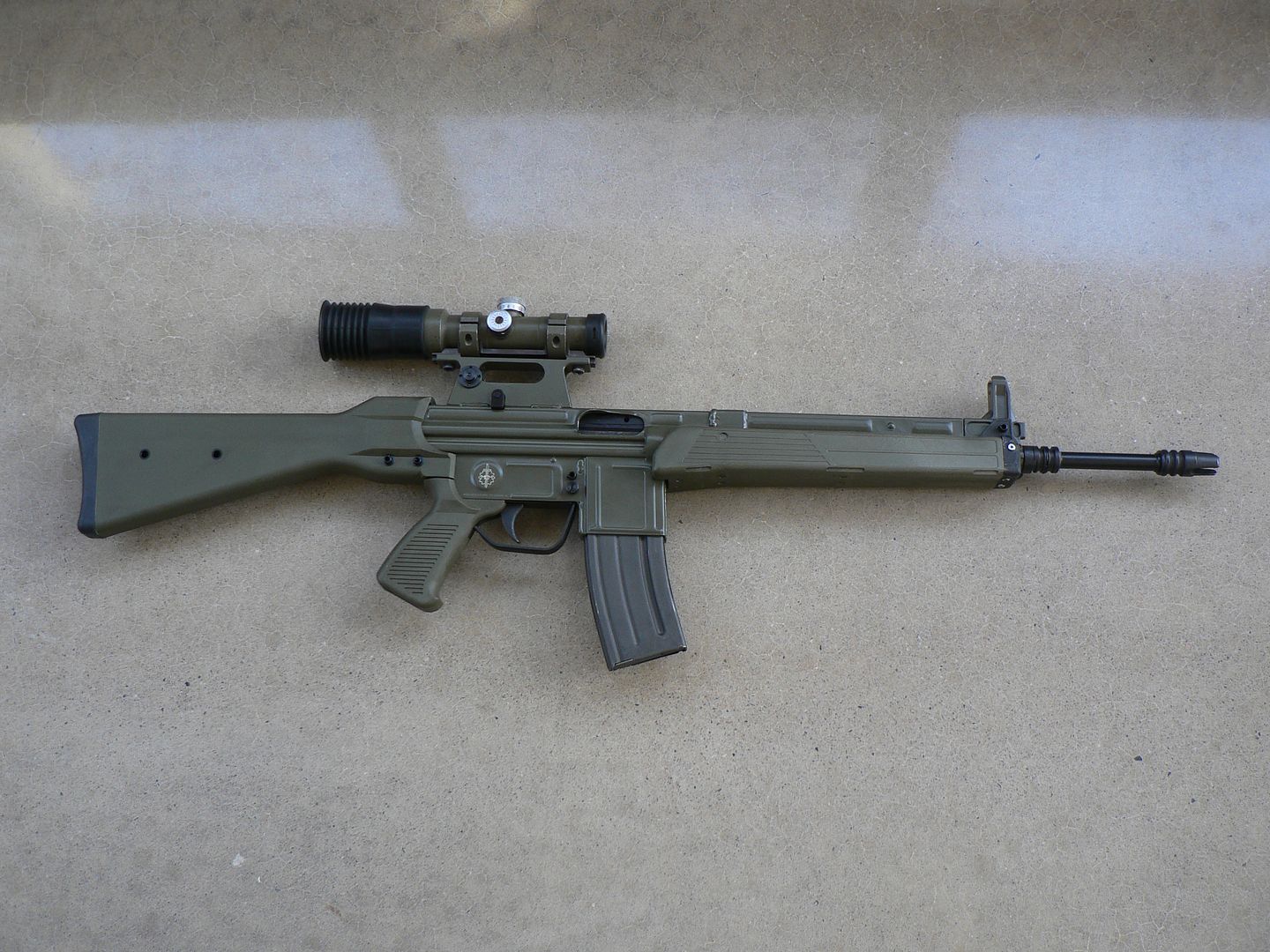
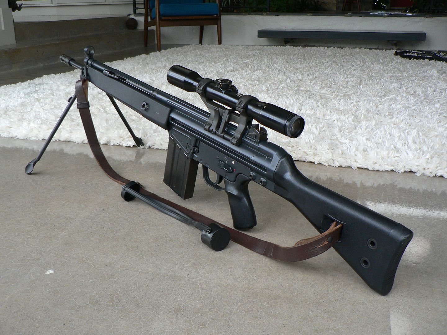
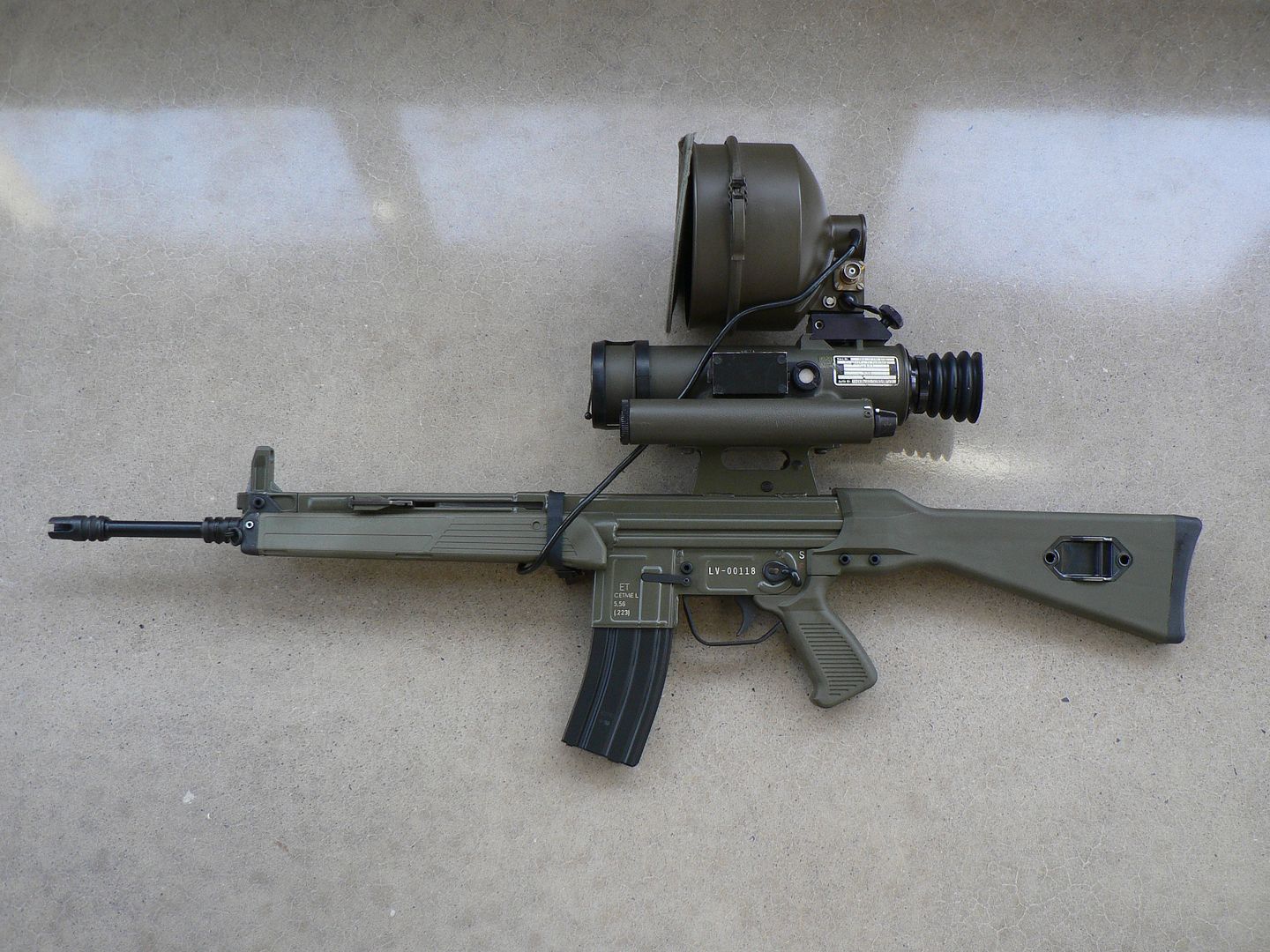
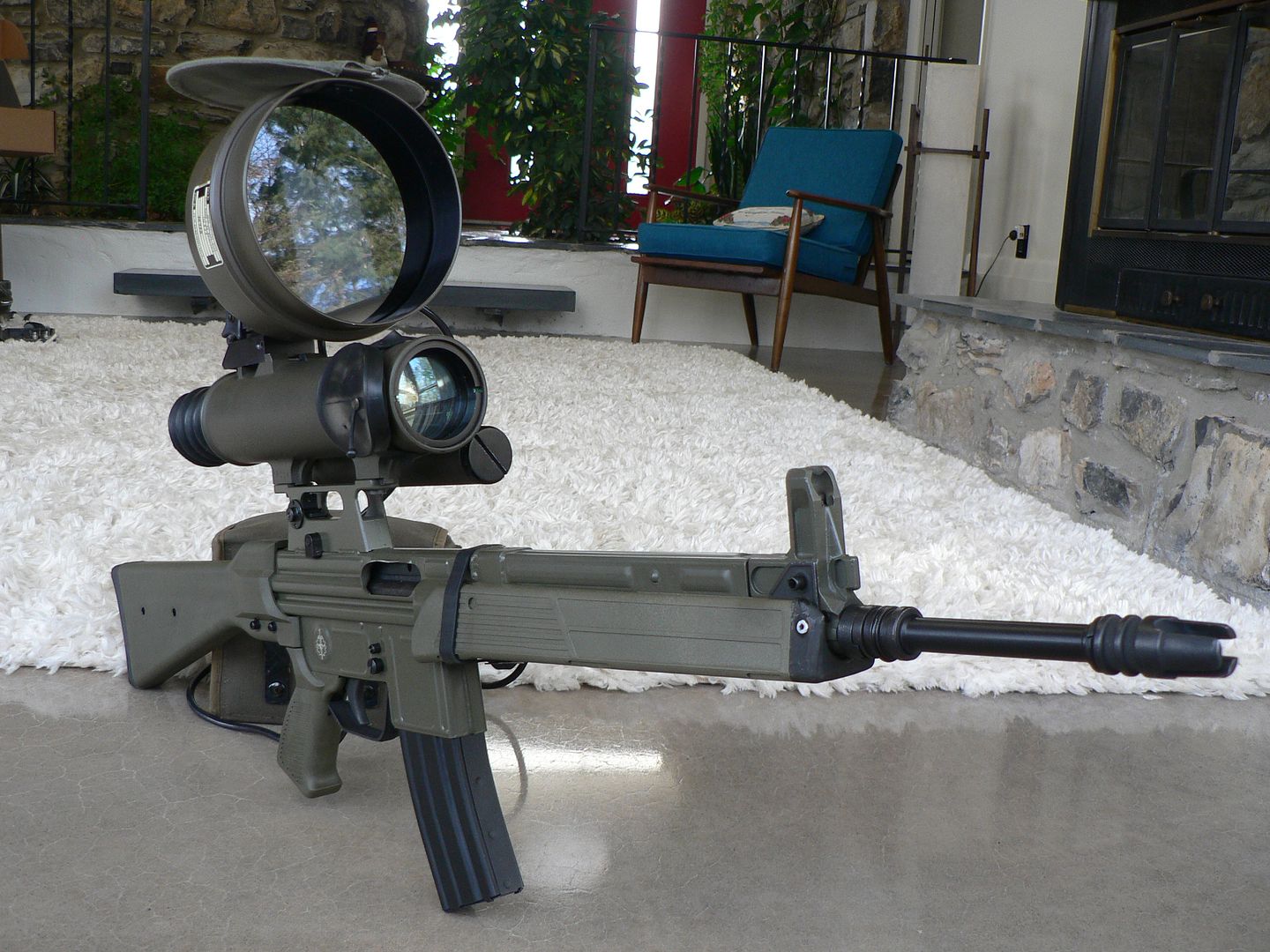
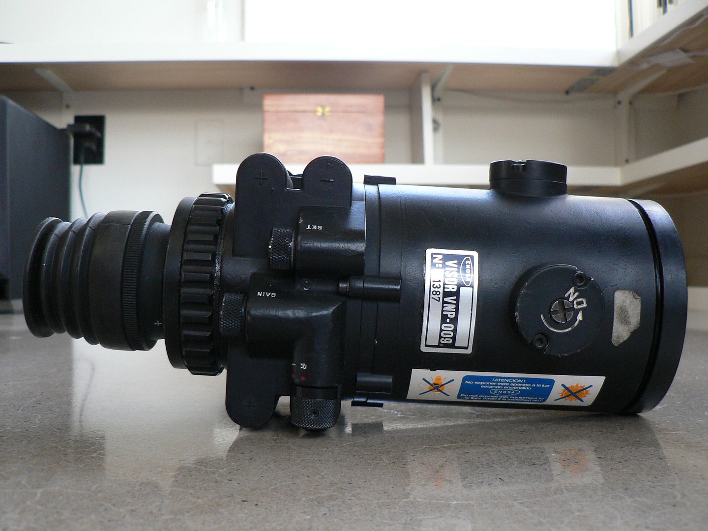
Right side:
On this side we see the right side battery compartment. It too holds two AA batteries.
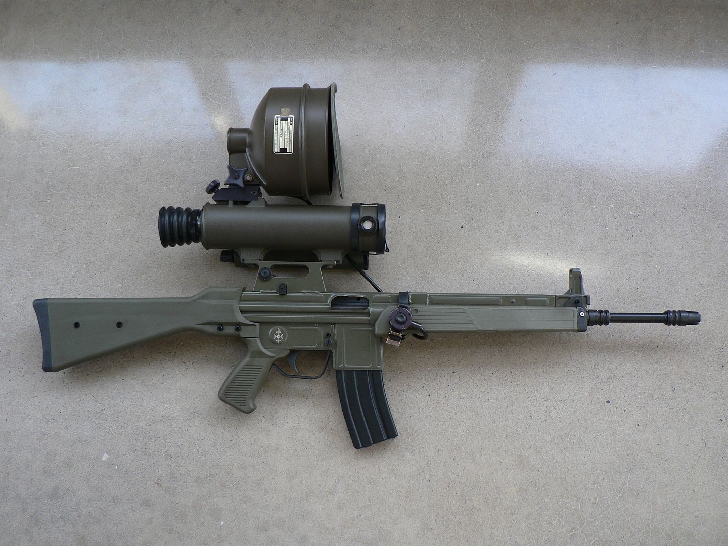
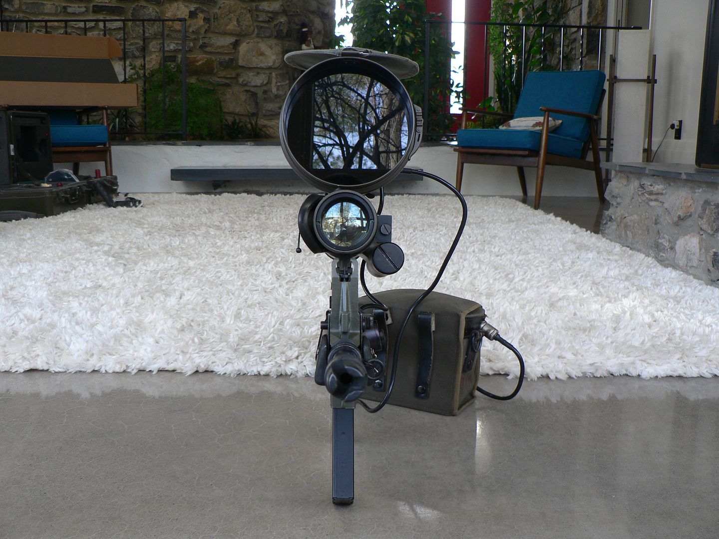
Top:
Just as we have the windage adjustment on the left side, we have the elevation adjustment on top. "DN" means "DOWN". In Spanish "Down" is "Abajo". Each click counterclockwise will move the point of impact down by 2.5cm at 100m. Note that neither the windage nor elevation are quick adjustment knobs as they can only be adjusted by means of a tool (the manual says to use a coin and that makes sense because the slots are so wide that a regular screwdriver would be impractical). This thing was not meant for precision shooting but rather to be used against a man sized target at night. It is generally sighted in at a particular range and you use Kentucky windage and Arkansas elevation beyond that. There are some other things of interest in this picture but we'll look at those a bit closer in just a bit.
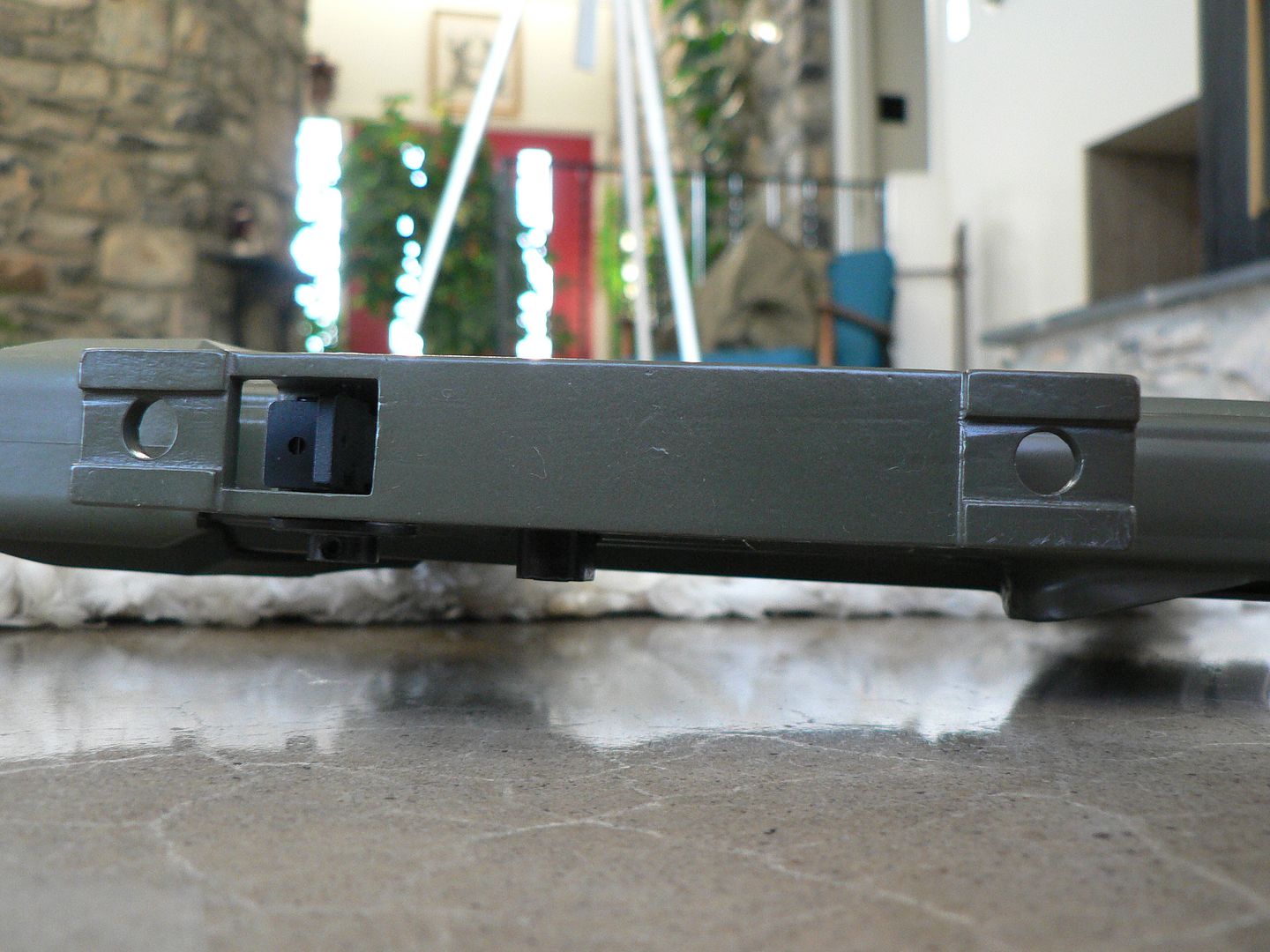
Bottom:

All we have going on here are the covers for the left and right side battery compartments and the NATO/STANAG adaptor mounted to the lugs molded into the scope body by way of two slotted screws. It is here we will begin looking at things in detail.
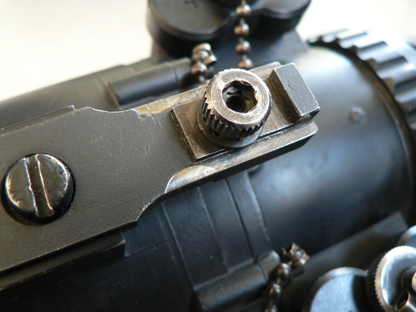
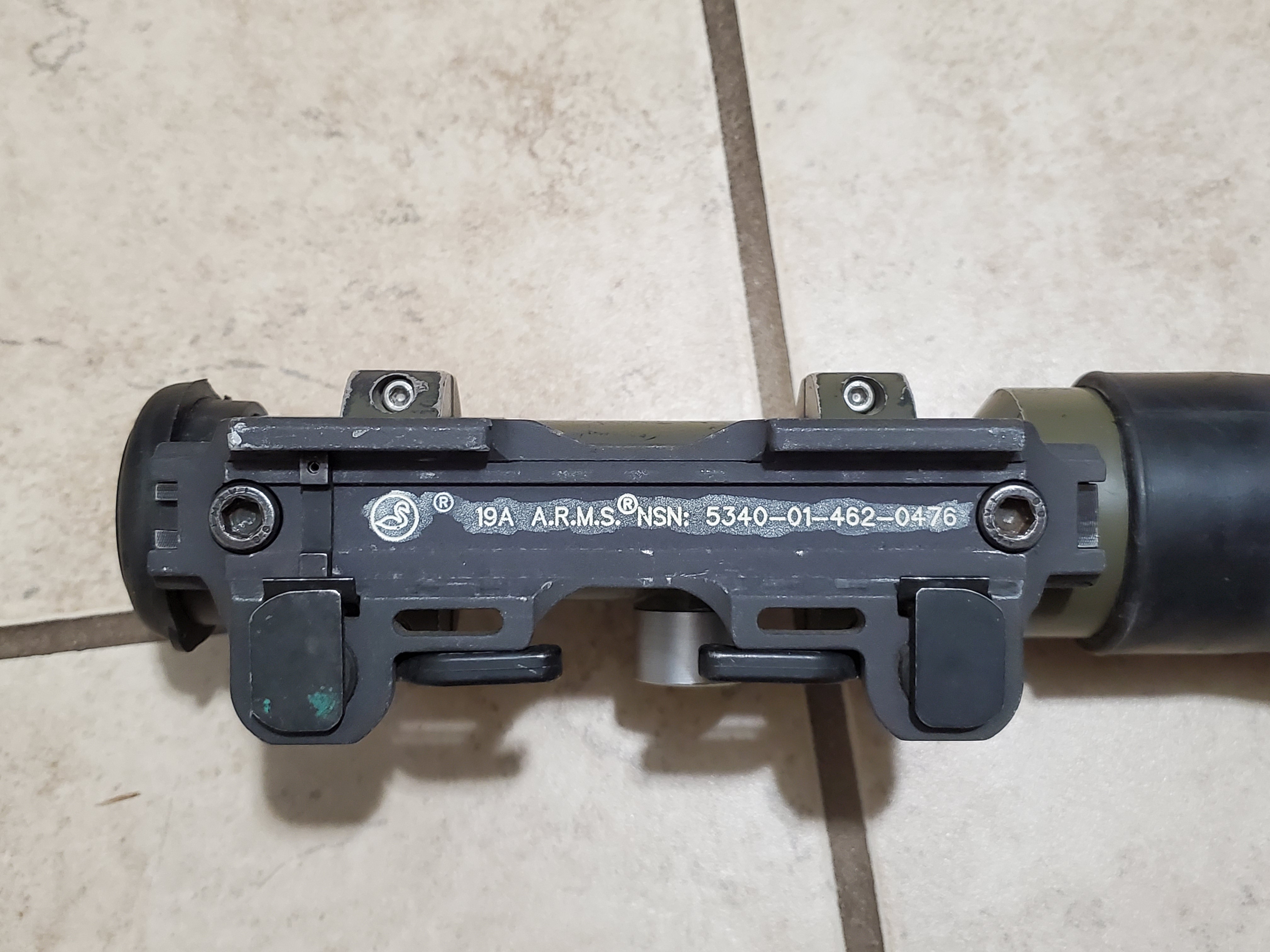
Here we see a side detail of the rear lug and NATO adaptor:
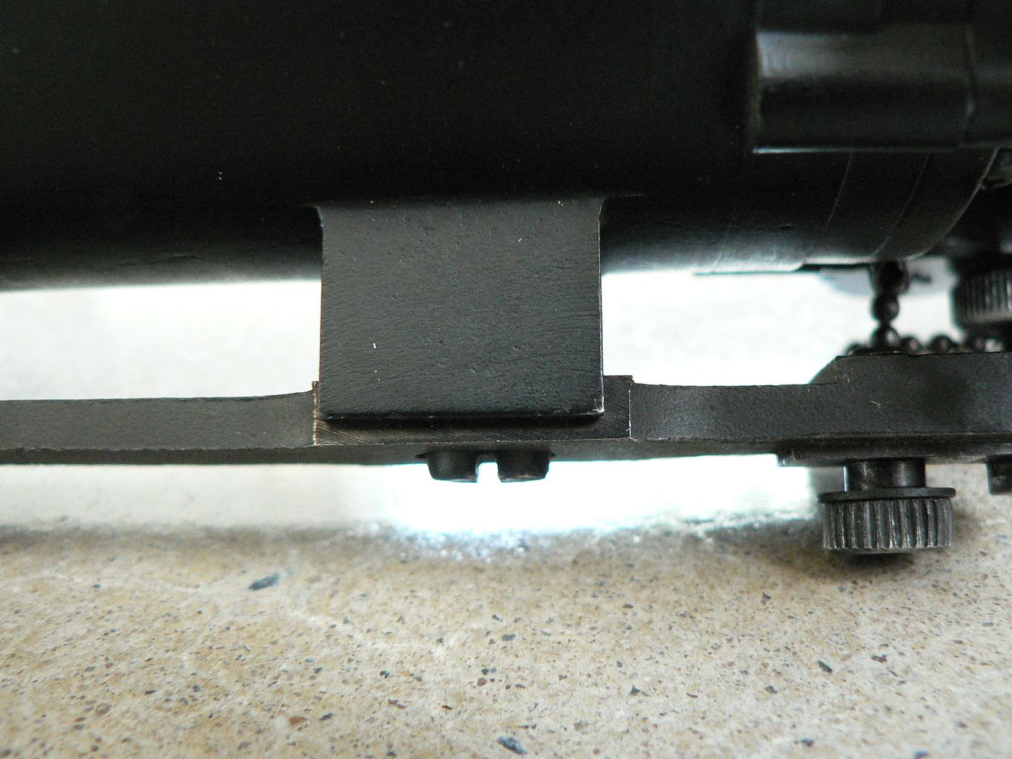
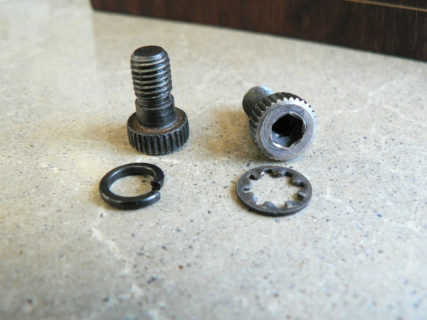
If you compare this adaptor to the one mounted on the Model F scope, you'll immediately see that it is different and purpose made for this scope. But, just as with the Model F, this scope can be mounted on different adaptors to be used in different applications. Towards the right of frame can be seen one of the splined cap screws used to mount the unit to the CETME LV. Just as on the Model F, these cap screws are also tightened using a 3/16" hex wrench.
Here's a look at the bottom front of the NATO adaptor (the rear is an almost identical mirror image):
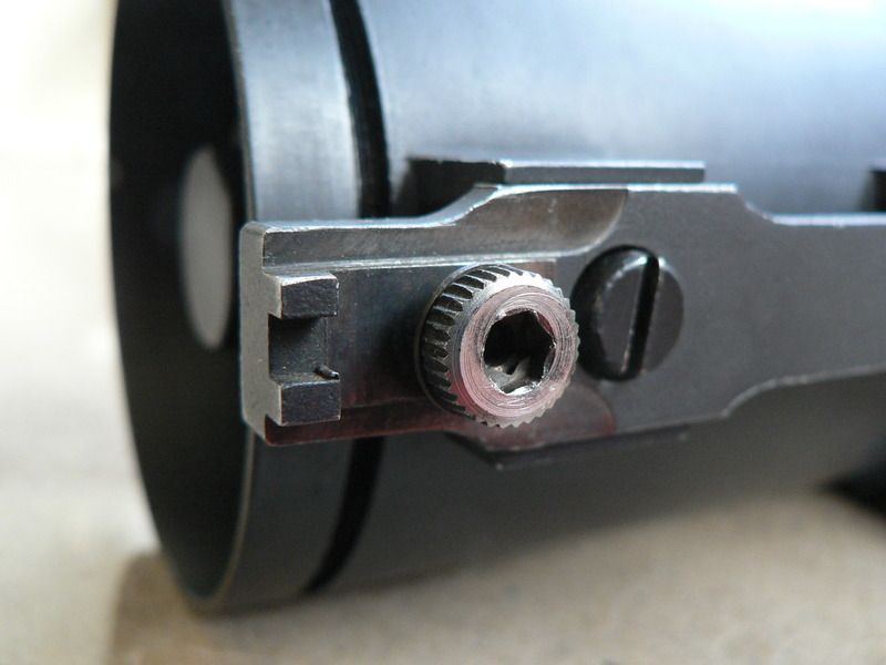
Starting on the left, the two blocky finger-like projections fit over the front edge of the mounting point on the rifle to precisely locate it in the proper position front to back on the rifle.
Moving right, we see the hex-head cap screw used to mount the unit on the rifle and then we come to the slotted screw used to attach the NATO adaptor to the scope. Also notice the two machined steps on either side of the cap screw, each running from front to back and ending in an inside radius. The purpose of these steps is to precisely align the adaptor side to side with the mounting point on the rifle.
The adaptor on the scope and the mounting point on the rifle's rear sight base are so perfectly machined that there is absolutely NO movement front to rear or side to side when you fit them together. Theoretically, this means it will maintain zero no matter how many times the optic is removed and remounted. But we don't live in a theoretical world now do we? Please don't think I'm trying to bash this setup and I'm sure it works very well but I cannot help but think that repeated switching out of optics in a real world field setting is a less than ideal design. I just don't think it's very practical.
If the above is at all confusing to you, just study the two pictures below. They show the bottom of the scope adaptor and the top of the mounting point on the rifle one after the other. By comparing them, you'll easily see how everything fits together:
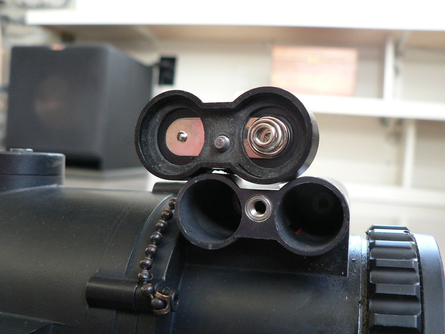
Here's a closeup of the left side battery box cover:

The right side cover looks the same. It's marked for polarity so that you don't put the batteries in the wrong way around. The little ball chain keeps the cover tethered so you won't loose it. The phillips screw only serves to attach the chain and has nothing to do with holding the cover in place. However, the phillips screw IS screwed to the cover retaining device which is itself a thumb screw. Lots of screwing going on here...….
To remove the cover, just loosen the thumbscrew by turning it counterclockwise a few times and off it comes:
The thumb screw is captive and cannot be removed from the cover. Note that it is also off center. This prevents you from attaching the battery box cover the wrong way around. A rubber gasket is to the inside of the cover to seal the battery compartment.
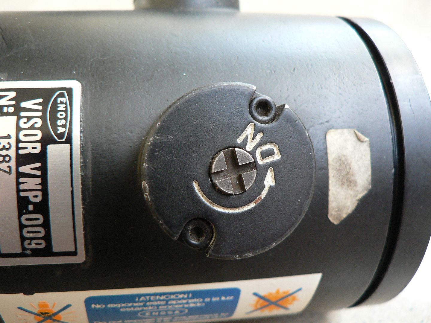
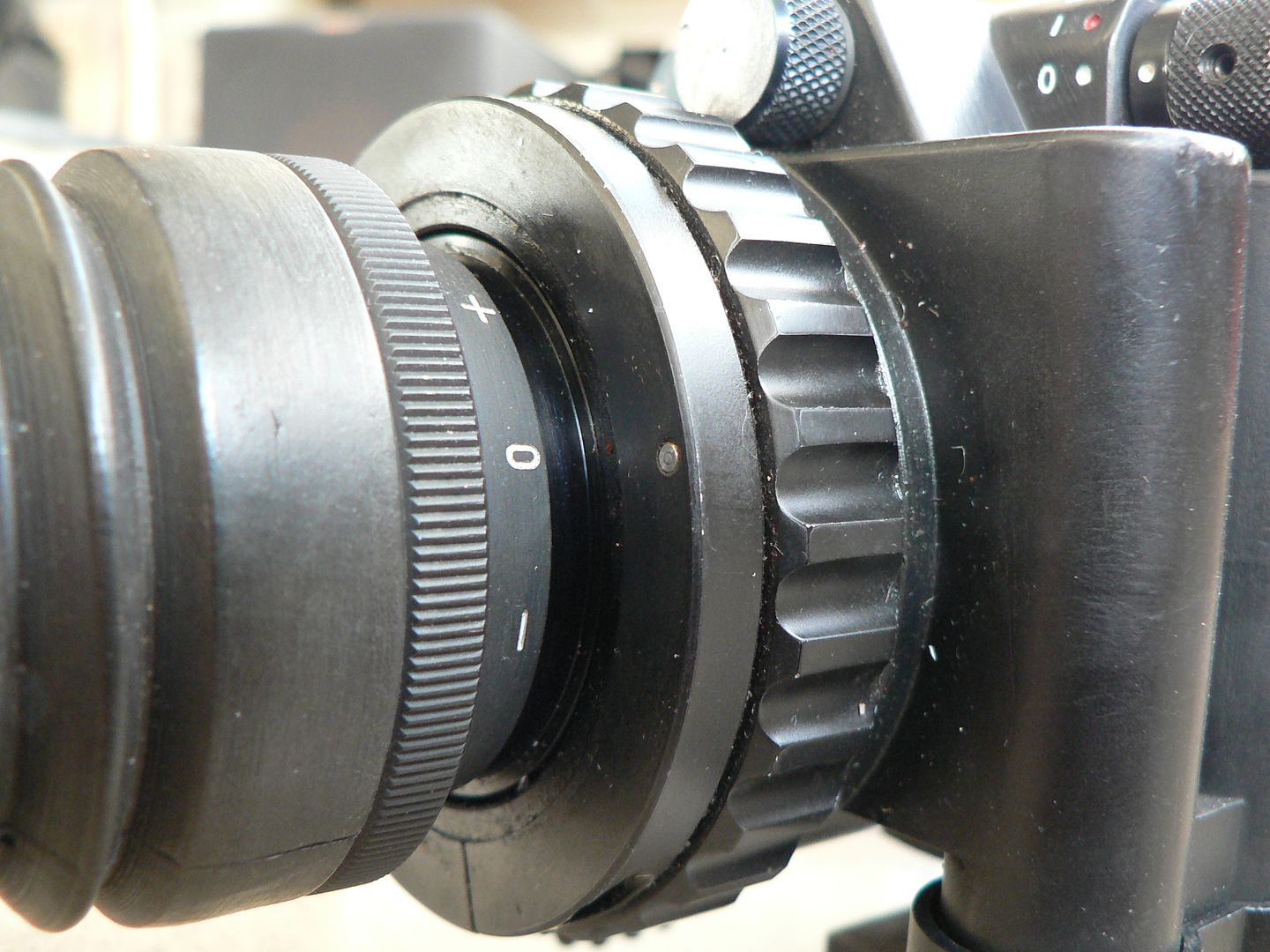
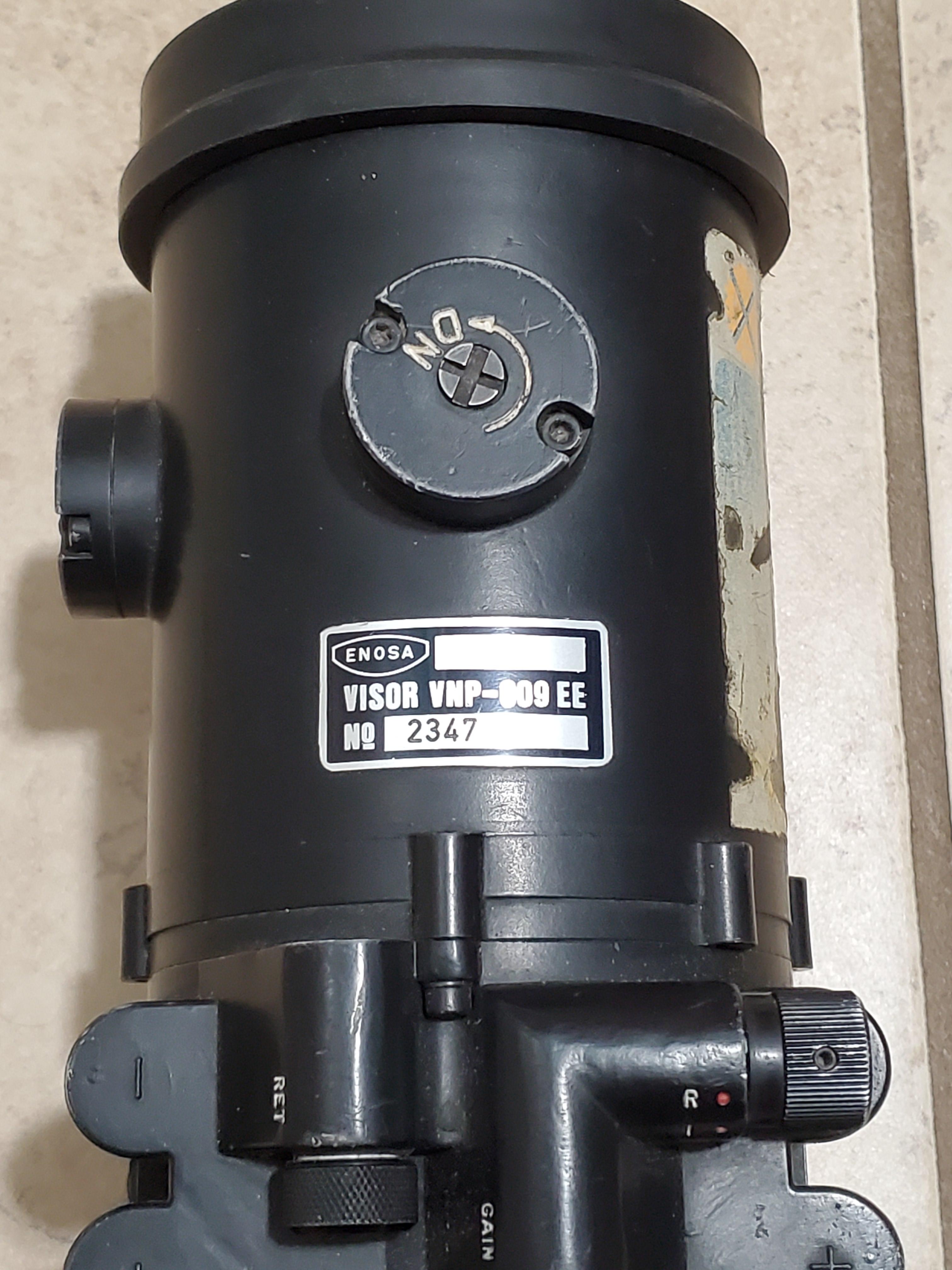
On top of the scope body, there are three controls. Facing towards the right side of the unit with markings visible from the rear is the power control knob
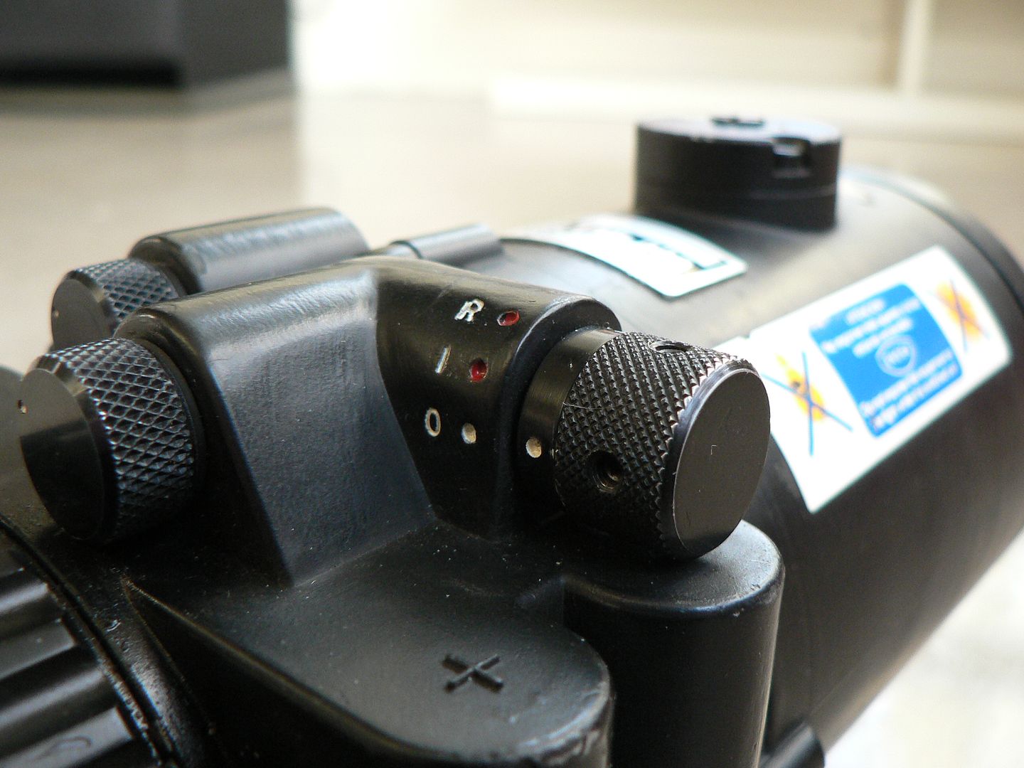
It is shown in the "OFF" position (white dot and "0"). ALWAYS make sure that the knob is in this position before you insert batteries and ALWAYS ensure that it is returned to this position as soon as you are finished using the scope.
--Turning the knob to the next position, a red dot and white "l", turns the intensifier tube on but the reticle lamp is still off. This position is used only for observation at night as you will see no aiming point. NEVER EVER turn the knob to this position without either the lens cover or the daylight filter set to Position 1 in place AND the GAIN knob turned to its lowest setting. If you turn the unit on in bright light, artificial or natural, without the lens cap or filter in place, you will, at a minimum, drastically reduce the life of the intensifier tube. Even worse, you may outright burn it out and trust me, you do not want to know the labor and expense of replacing it. You have been warned! As for the GAIN knob, keep reading for instructions regarding its use.
--Turning the knob to the last position, a red dot and white "R", turns on both the intensifier tube and the reticle. This position is used for aiming and firing. NEVER turn the knob to this position unless heeding the warning above. Additionally, ensure that the reticle brightness knob is turned down to its lowest setting (keep reading for more on that).
--When you are finished using the VNP-009, ALWAYS return the power knob to the "OFF" setting.
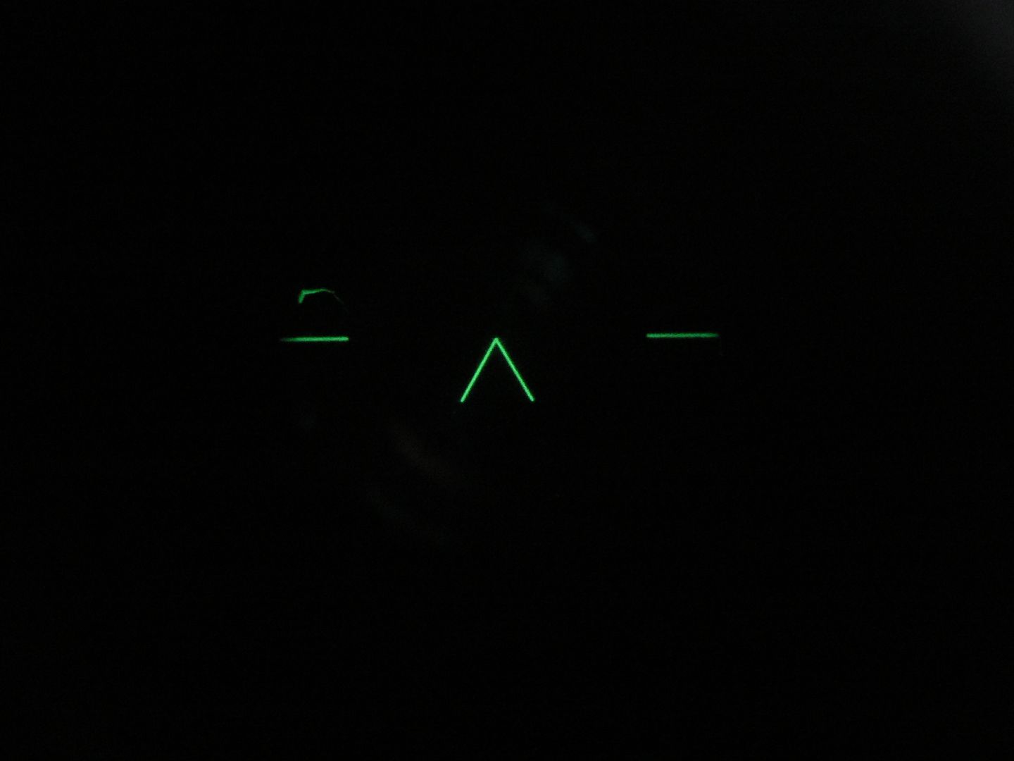
Facing to the rear with identification markings visible from the left side are the RETICLE and GAIN knobs:
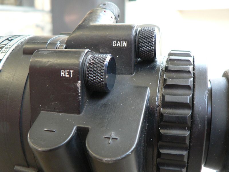
The knob marked "RET" controls how bright the reticle is. Any time you are ready to turn the reticle on, make sure the knob is turned counterclockwise as far as possible first. This is the lowest intensity position. The knob has no detents and is infinitely adjustable. Turn the intensity up only as high as is needed to clearly see the reticle. If left at too high a setting for too long, it WILL damage the intensifier tube. When finished using the reticle ALWAYS return the knob to the lowest intensity setting.
Here we see both the reticle brightness knob (on the left) and the GAIN adjustment knob (on the right) set to minimum:
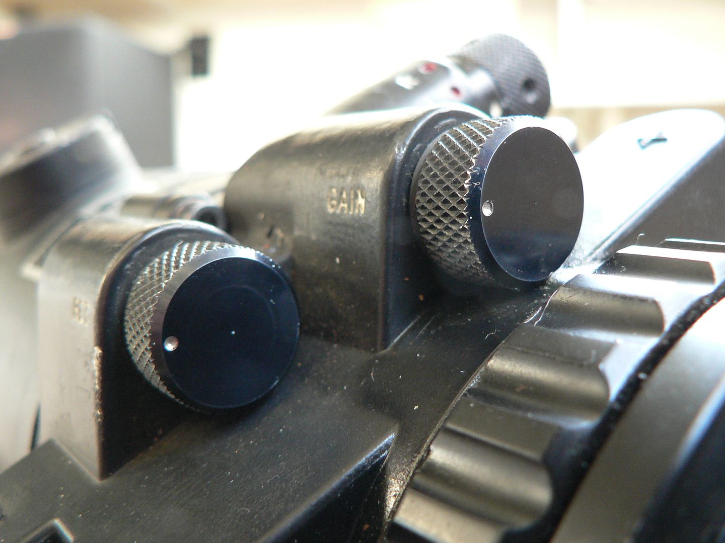
The GAIN adjustment is best described as a fine tuning knob for image intensity and contrast. In essence, it's a rheostat that adjusts how much power is supplied to the intensifier tube. Turning it clockwise raises the setting. The higher the setting, the more the photons entering the objective lens get amplified and the brighter the image. So why wouldn't you always want the brightest image? Well, out in the boonies with little ambient light, you do want the gain turned up. However, in a more urban area with more ambient light or on a moon lit cloudless ight, having the gain set way up may give you too bright an image resulting in a washed out image with little contrast. This is also hard on the intensifier tube. Consequently, ALWAYS have the GAIN knob at its lowest setting when you power on the scope and slowly turn it up until you have a clear image, no more. Additionally, ALWAYS return the GAIN knob to its lowest setting before powering down the scope.
--IMPORTANT: ALWAYS set the GAIN first followed by the reticle.
--IMPORTANT: ALWAYS store the scope with batteries removed, lens cover or daylight filter set to Position1 in place over the objective lens, power knob in the "OFF" position and both the GAIN and RETICLE knobs set to minimum. Additionally, place the VNP-009 in its nylon storage bag prior to placing it in the transit case.
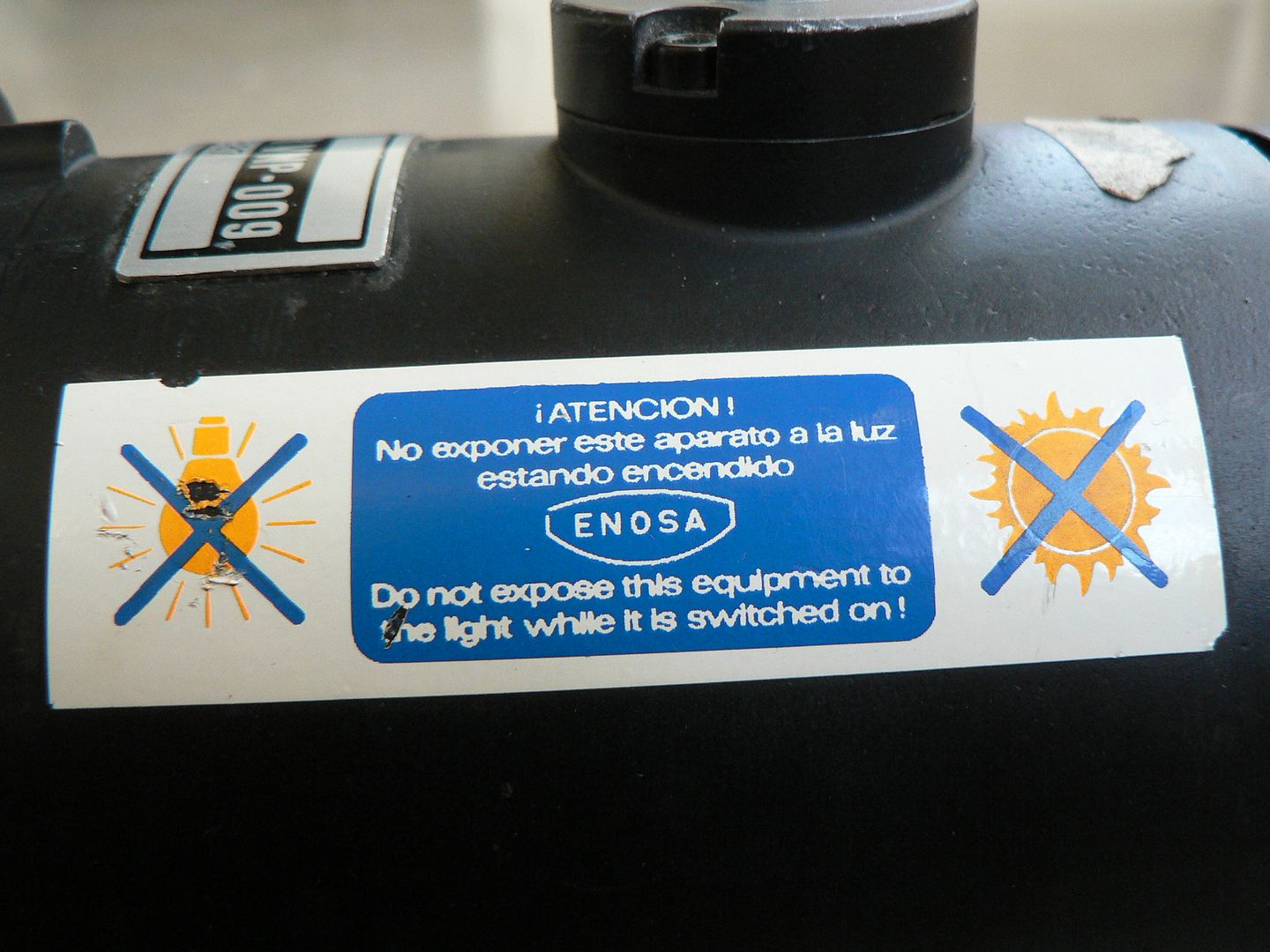
--NEVER point the scope at the sun even when powered off and, just to be safe, don't expose the objective lens to bright light for at least 15 minutes after switching the unit off just in case there is any residual power in the intensifier tube that needs to bleed off. Older Gen 0 and Gen 1 tubes held a charge for a while after being switched off and were still light sensitive. I don't think that's the case with a Gen 2 but it can't hurt to err on the side of caution.
Follow the above directions and your VNP-009 will last you many, many hours of use. In fact, unless your are using the thing all night every night, it'll probably last your lifetime. Just always remember that every single photon the intensifier tube processes kills it just a little bit. These things have a finite lifespan no matter how much care you give them but there is no sense in being careless. Always think before touching any controls and really KNOW what you are doing before you do it.
There is more to cover and we'll continue on in the next post but the above covers the most important topics with regards to not destroying your VNP-009. But I need to get to bed for now. I'll be back tomorrow or the next day.
You read that right, this is a Gen2 unit and I believe it is most likely made in the Unites States or, at the very least, of US and British components. The entire front lens block is essentially identical to an AN/PVS-4 and all controls are in English. The feel and operation of it is also smoother and, for lack of a better term, more sophisticated than the Model F scope. The Quality of the image is also as good as US Gen 2 equipment of the era. The round lug with marked with an arrow and "RT" (the abbreviation for "RIGHT") is the windage adjustment and it clicks as you turn it with a coin or similar. Each click counterclockwise moves the point of impact 2.5cm to the right at 100m. The Spanish word for "Right" is "Dereche". Farther back, the two vertical tubes are the left side battery compartment which holds two AA batteries.
Right side:
On this side we see the right side battery compartment. It too holds two AA batteries.
Top:
Just as we have the windage adjustment on the left side, we have the elevation adjustment on top. "DN" means "DOWN". In Spanish "Down" is "Abajo". Each click counterclockwise will move the point of impact down by 2.5cm at 100m. Note that neither the windage nor elevation are quick adjustment knobs as they can only be adjusted by means of a tool (the manual says to use a coin and that makes sense because the slots are so wide that a regular screwdriver would be impractical). This thing was not meant for precision shooting but rather to be used against a man sized target at night. It is generally sighted in at a particular range and you use Kentucky windage and Arkansas elevation beyond that. There are some other things of interest in this picture but we'll look at those a bit closer in just a bit.
Bottom:
All we have going on here are the covers for the left and right side battery compartments and the NATO/STANAG adaptor mounted to the lugs molded into the scope body by way of two slotted screws. It is here we will begin looking at things in detail.
Here we see a side detail of the rear lug and NATO adaptor:
If you compare this adaptor to the one mounted on the Model F scope, you'll immediately see that it is different and purpose made for this scope. But, just as with the Model F, this scope can be mounted on different adaptors to be used in different applications. Towards the right of frame can be seen one of the splined cap screws used to mount the unit to the CETME LV. Just as on the Model F, these cap screws are also tightened using a 3/16" hex wrench.
Here's a look at the bottom front of the NATO adaptor (the rear is an almost identical mirror image):
Starting on the left, the two blocky finger-like projections fit over the front edge of the mounting point on the rifle to precisely locate it in the proper position front to back on the rifle.
Moving right, we see the hex-head cap screw used to mount the unit on the rifle and then we come to the slotted screw used to attach the NATO adaptor to the scope. Also notice the two machined steps on either side of the cap screw, each running from front to back and ending in an inside radius. The purpose of these steps is to precisely align the adaptor side to side with the mounting point on the rifle.
The adaptor on the scope and the mounting point on the rifle's rear sight base are so perfectly machined that there is absolutely NO movement front to rear or side to side when you fit them together. Theoretically, this means it will maintain zero no matter how many times the optic is removed and remounted. But we don't live in a theoretical world now do we? Please don't think I'm trying to bash this setup and I'm sure it works very well but I cannot help but think that repeated switching out of optics in a real world field setting is a less than ideal design. I just don't think it's very practical.
If the above is at all confusing to you, just study the two pictures below. They show the bottom of the scope adaptor and the top of the mounting point on the rifle one after the other. By comparing them, you'll easily see how everything fits together:
Here's a closeup of the left side battery box cover:
The right side cover looks the same. It's marked for polarity so that you don't put the batteries in the wrong way around. The little ball chain keeps the cover tethered so you won't loose it. The phillips screw only serves to attach the chain and has nothing to do with holding the cover in place. However, the phillips screw IS screwed to the cover retaining device which is itself a thumb screw. Lots of screwing going on here...….
To remove the cover, just loosen the thumbscrew by turning it counterclockwise a few times and off it comes:
The thumb screw is captive and cannot be removed from the cover. Note that it is also off center. This prevents you from attaching the battery box cover the wrong way around. A rubber gasket is to the inside of the cover to seal the battery compartment.
On top of the scope body, there are three controls. Facing towards the right side of the unit with markings visible from the rear is the power control knob
It is shown in the "OFF" position (white dot and "0"). ALWAYS make sure that the knob is in this position before you insert batteries and ALWAYS ensure that it is returned to this position as soon as you are finished using the scope.
--Turning the knob to the next position, a red dot and white "l", turns the intensifier tube on but the reticle lamp is still off. This position is used only for observation at night as you will see no aiming point. NEVER EVER turn the knob to this position without either the lens cover or the daylight filter set to Position 1 in place AND the GAIN knob turned to its lowest setting. If you turn the unit on in bright light, artificial or natural, without the lens cap or filter in place, you will, at a minimum, drastically reduce the life of the intensifier tube. Even worse, you may outright burn it out and trust me, you do not want to know the labor and expense of replacing it. You have been warned! As for the GAIN knob, keep reading for instructions regarding its use.
--Turning the knob to the last position, a red dot and white "R", turns on both the intensifier tube and the reticle. This position is used for aiming and firing. NEVER turn the knob to this position unless heeding the warning above. Additionally, ensure that the reticle brightness knob is turned down to its lowest setting (keep reading for more on that).
--When you are finished using the VNP-009, ALWAYS return the power knob to the "OFF" setting.
Facing to the rear with identification markings visible from the left side are the RETICLE and GAIN knobs:
The knob marked "RET" controls how bright the reticle is. Any time you are ready to turn the reticle on, make sure the knob is turned counterclockwise as far as possible first. This is the lowest intensity position. The knob has no detents and is infinitely adjustable. Turn the intensity up only as high as is needed to clearly see the reticle. If left at too high a setting for too long, it WILL damage the intensifier tube. When finished using the reticle ALWAYS return the knob to the lowest intensity setting.
Here we see both the reticle brightness knob (on the left) and the GAIN adjustment knob (on the right) set to minimum:
The GAIN adjustment is best described as a fine tuning knob for image intensity and contrast. In essence, it's a rheostat that adjusts how much power is supplied to the intensifier tube. Turning it clockwise raises the setting. The higher the setting, the more the photons entering the objective lens get amplified and the brighter the image. So why wouldn't you always want the brightest image? Well, out in the boonies with little ambient light, you do want the gain turned up. However, in a more urban area with more ambient light or on a moon lit cloudless ight, having the gain set way up may give you too bright an image resulting in a washed out image with little contrast. This is also hard on the intensifier tube. Consequently, ALWAYS have the GAIN knob at its lowest setting when you power on the scope and slowly turn it up until you have a clear image, no more. Additionally, ALWAYS return the GAIN knob to its lowest setting before powering down the scope.
--IMPORTANT: ALWAYS set the GAIN first followed by the reticle.
--IMPORTANT: ALWAYS store the scope with batteries removed, lens cover or daylight filter set to Position1 in place over the objective lens, power knob in the "OFF" position and both the GAIN and RETICLE knobs set to minimum. Additionally, place the VNP-009 in its nylon storage bag prior to placing it in the transit case.
--NEVER point the scope at the sun even when powered off and, just to be safe, don't expose the objective lens to bright light for at least 15 minutes after switching the unit off just in case there is any residual power in the intensifier tube that needs to bleed off. Older Gen 0 and Gen 1 tubes held a charge for a while after being switched off and were still light sensitive. I don't think that's the case with a Gen 2 but it can't hurt to err on the side of caution.
Follow the above directions and your VNP-009 will last you many, many hours of use. In fact, unless your are using the thing all night every night, it'll probably last your lifetime. Just always remember that every single photon the intensifier tube processes kills it just a little bit. These things have a finite lifespan no matter how much care you give them but there is no sense in being careless. Always think before touching any controls and really KNOW what you are doing before you do it.
There is more to cover and we'll continue on in the next post but the above covers the most important topics with regards to not destroying your VNP-009. But I need to get to bed for now. I'll be back tomorrow or the next day.