Combloc
Stop Negassing me!!!!!
In this post, we'll be taking an up close and personal look at MarColMar's recently released CETME LV in 5.56/.223. For those of you not familiar with the CETME Model L, it was made in Spain and served as their standard 5.56mm infantry rifle from about the mid 1980's through the mid 1990's until being replaced by the German manufactured G36 rifle. BUT, this is not a History lesson so I'll leave it at that.
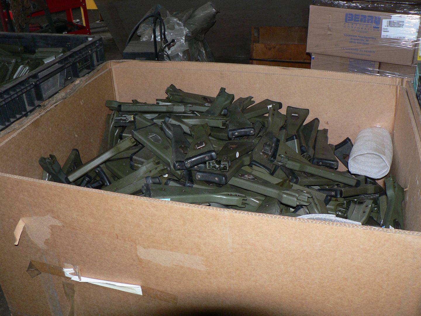
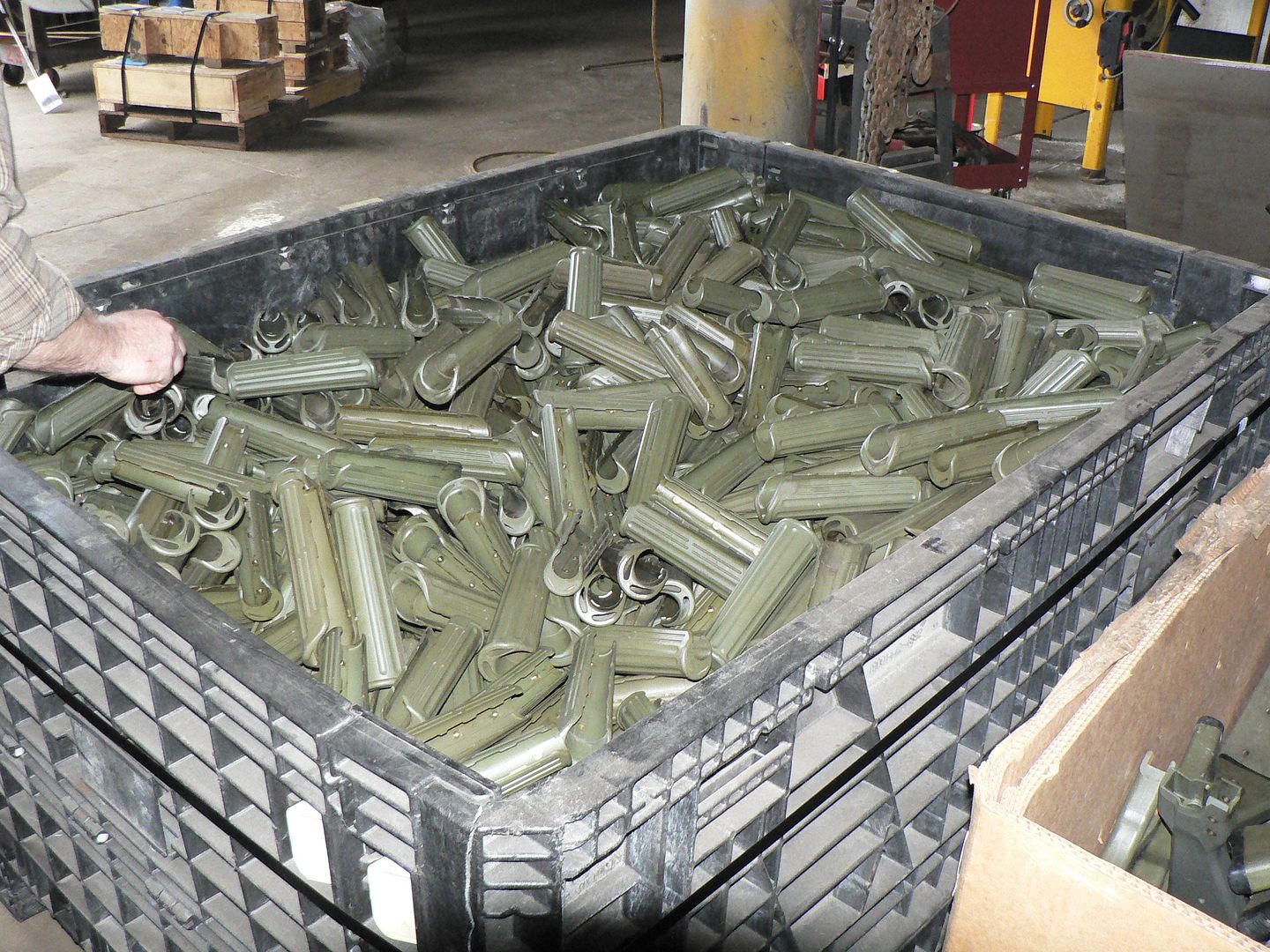
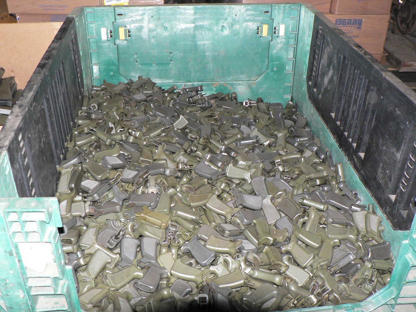
Fast forward until a few years ago when a little north of 10,000 5.56mm CETME rifles were removed from storage in Spain, scrapped and sold to the US market as parts kits. Of these, MarColMar ended up with approximately 10,000 kits in three versions. They are, from top to bottom, the LV, L and LC:
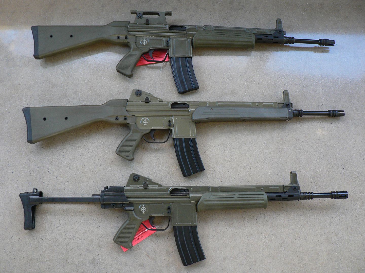
The vast majority of the kits were the standard fixed stock "L" version designed to be used primarily with iron sights and although many (but not all) did have a rear sight tower capable of having a scope mount attached, the optic mount seems to be vanishingly rare at this point. If you have one, please let me know as I'd LOVE to document it. If you are interested in the standard "L" version rebuilt by MarColMar, I wrote about one of those in-depth earlier this year and compared it to both a Hill and Mac kit rebuild and an original intact Spanish specimen. Just type the following into your favorite search engine and you'll immediately find links to it on multiple sites:
MarColMar and HMG Cetme L a Detailed Comparison
Also acquired by were some of the "LC" version. The primary difference of this version compared to the standard "L" model is a collapsible butt stock intended make it more compact for movement or stowage. Of the approximately 10,000 kits acquired by MarColMar, only 645 were of this variety. If you are interested in reading about the LC, I encourage you to read the article I've just recently written about this version. It can easily be found on this very forum by searching "MarColMar CETME LC (Carbine) In Detail". I enjoyed writing it and I hope you enjoy reading it if you are so inclined.
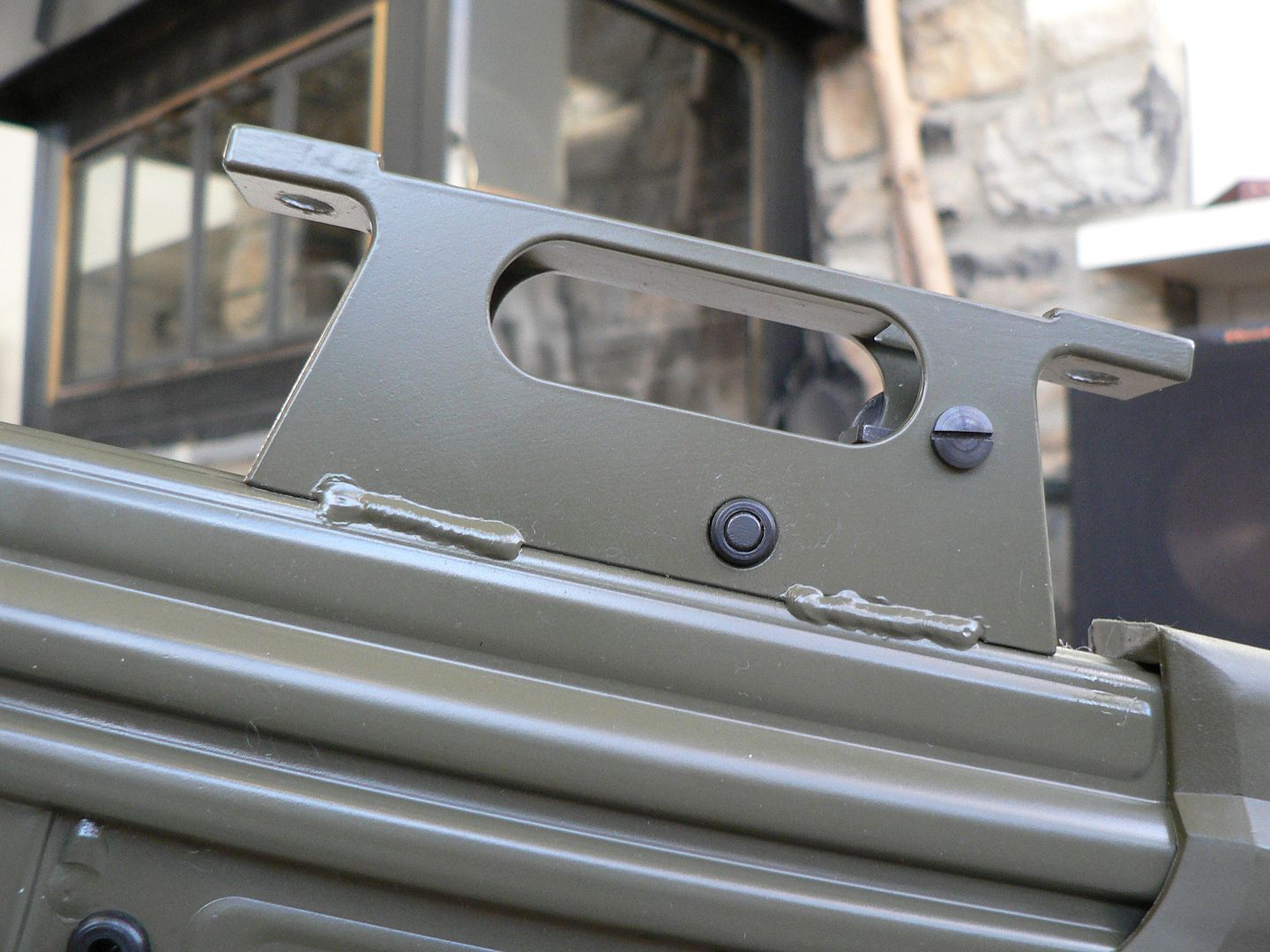
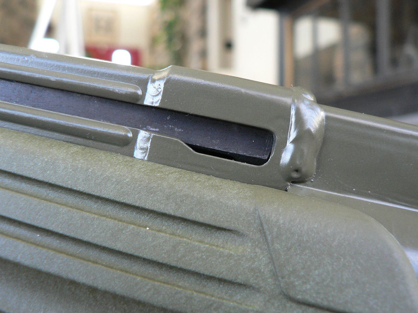
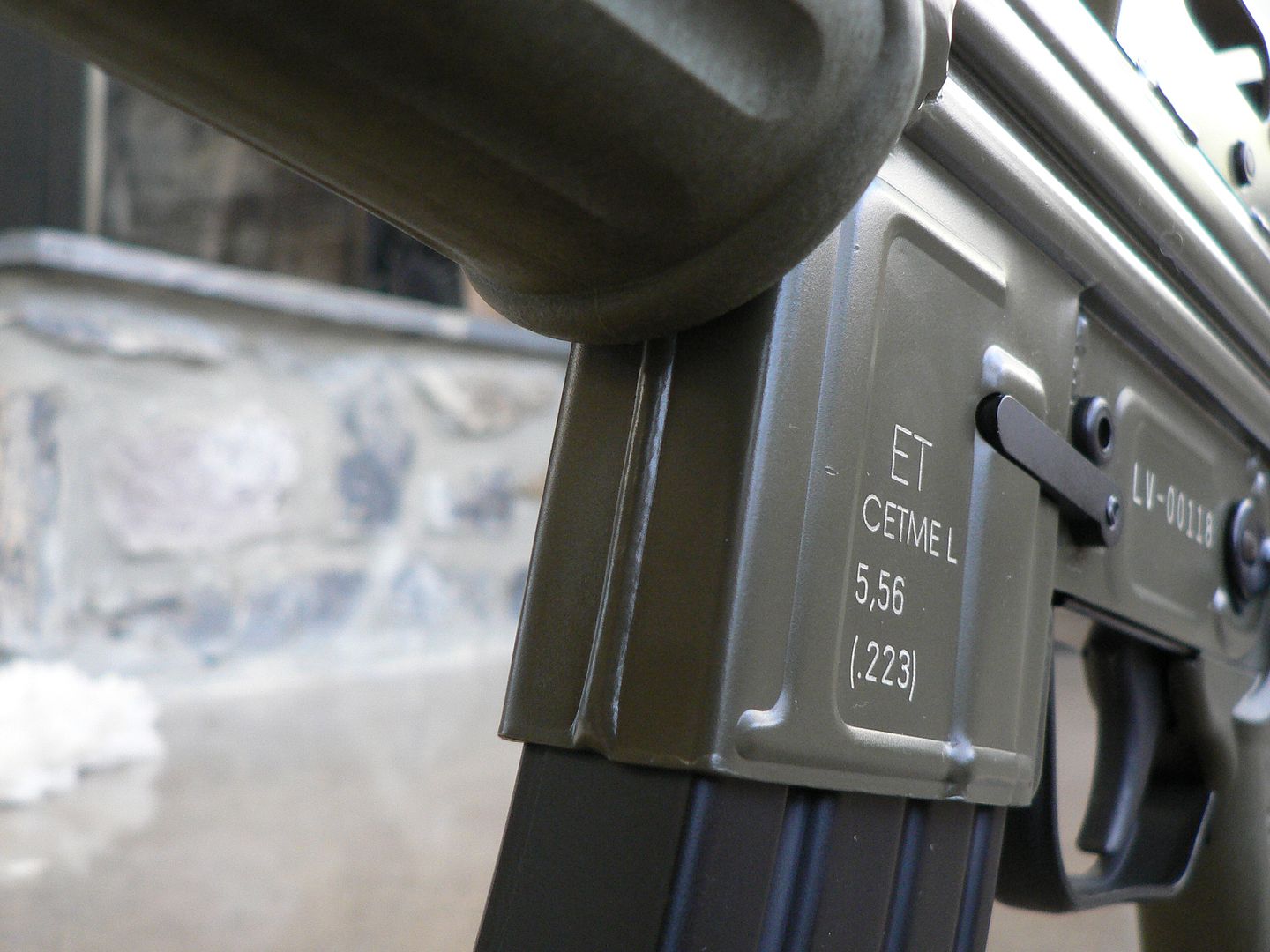
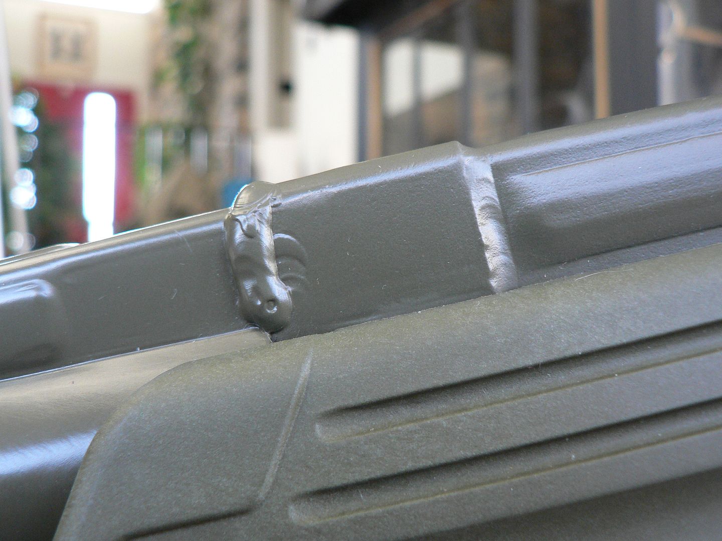
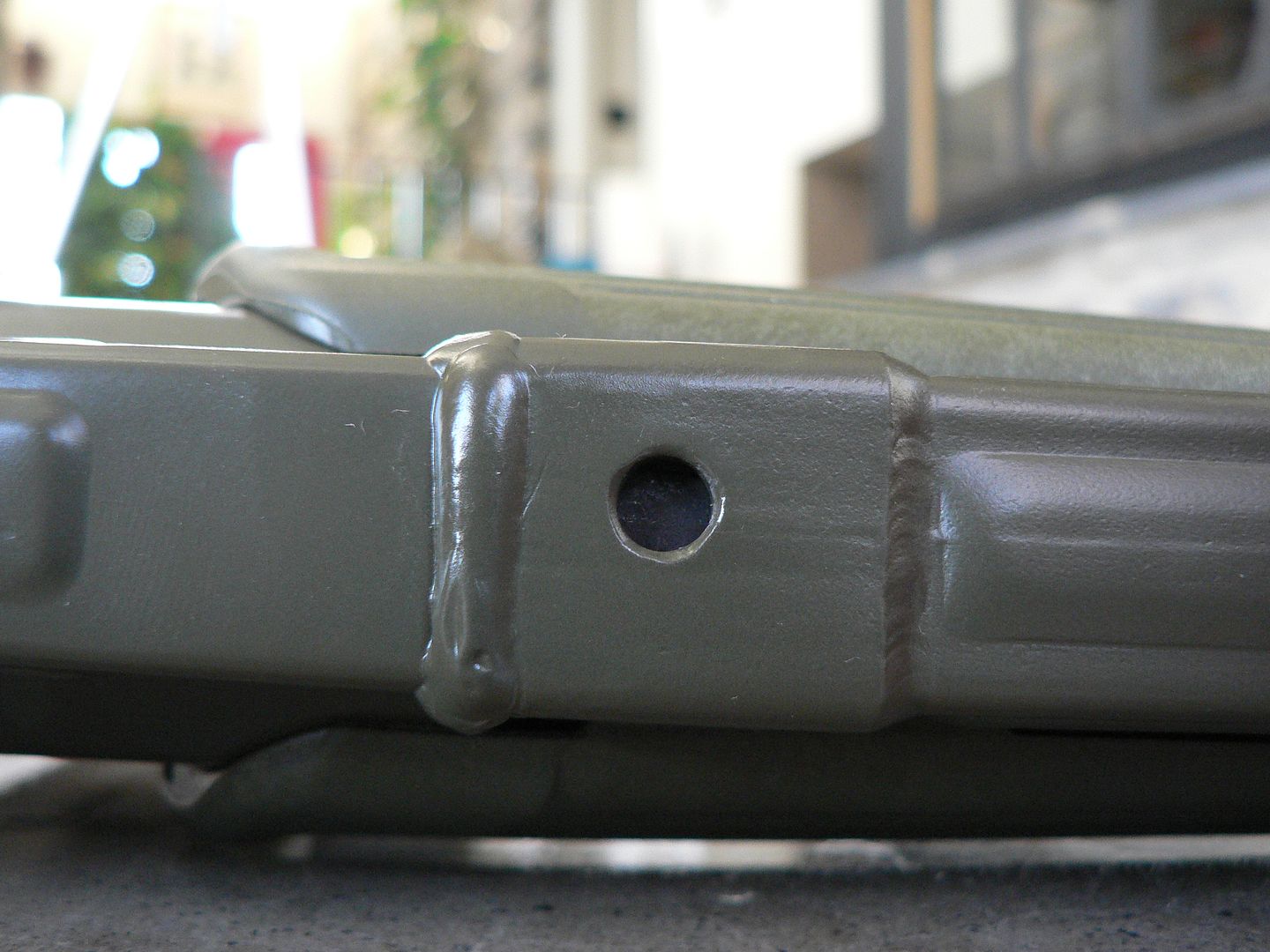
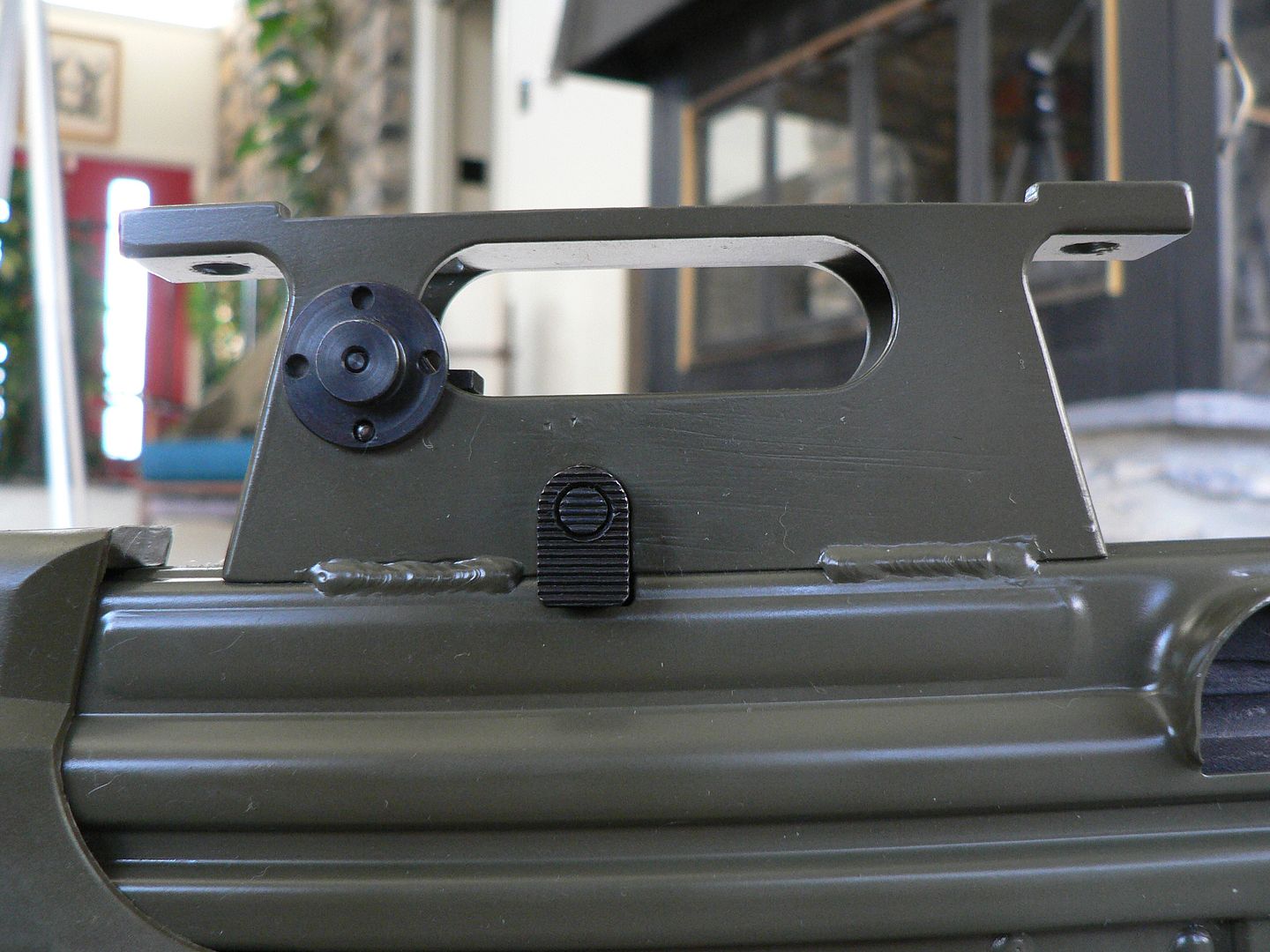
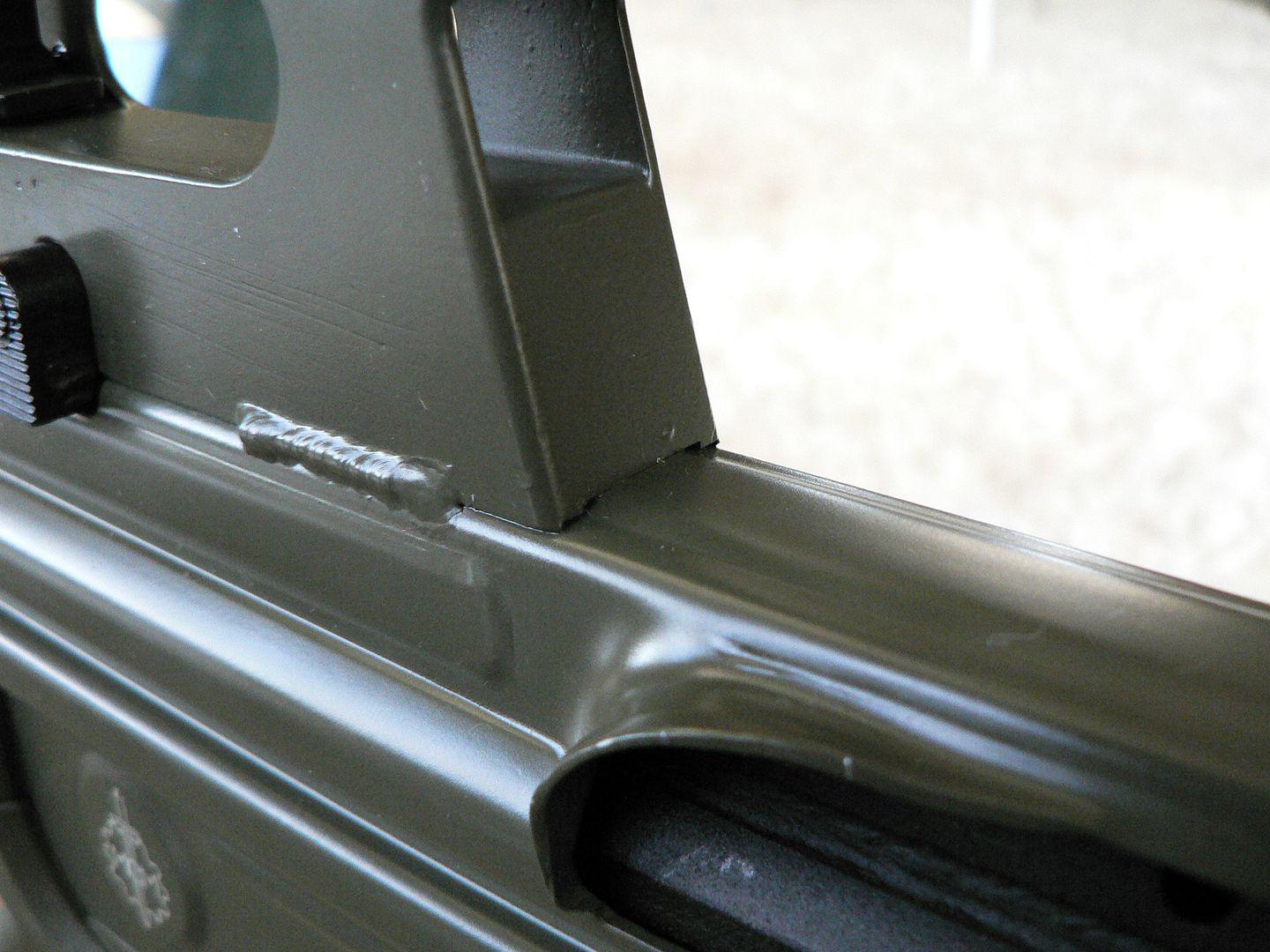
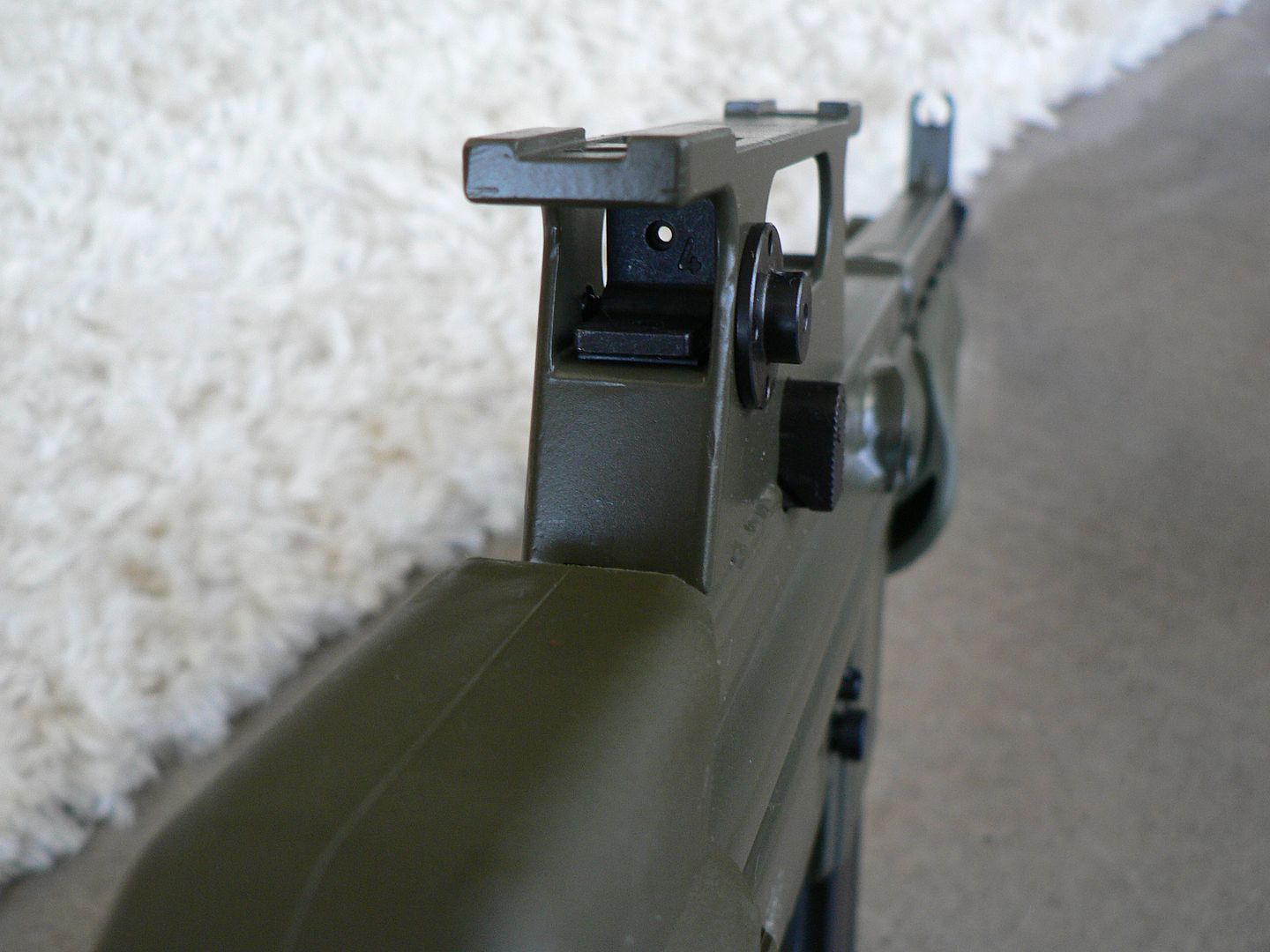
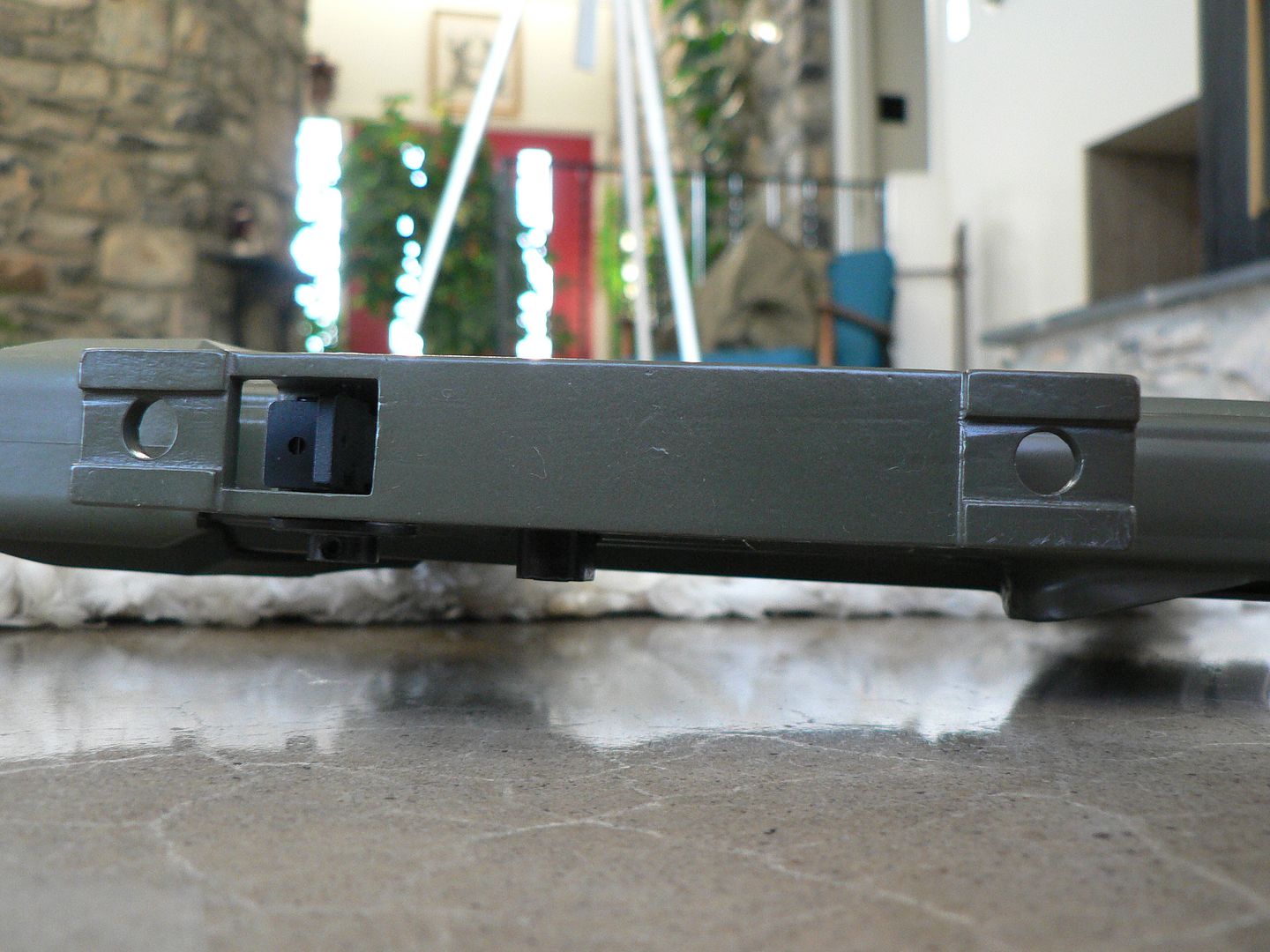
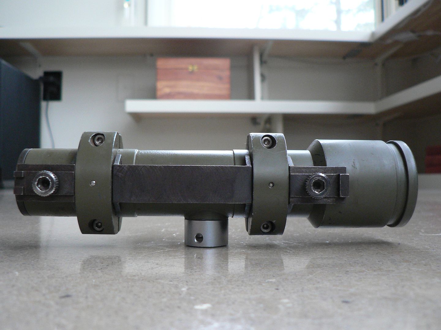
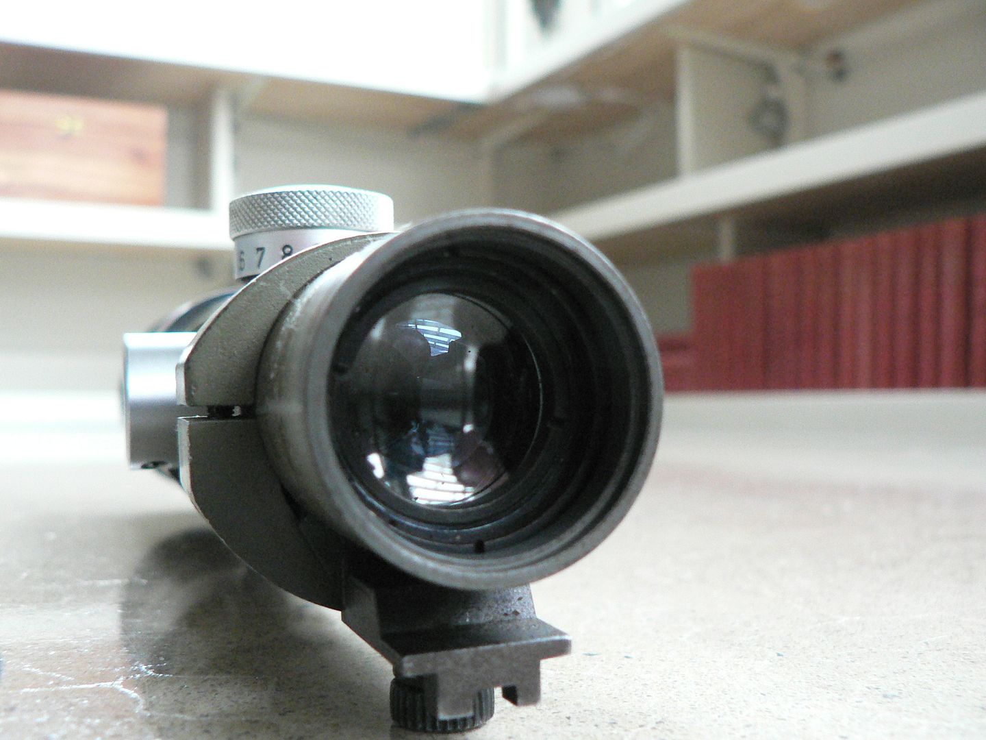
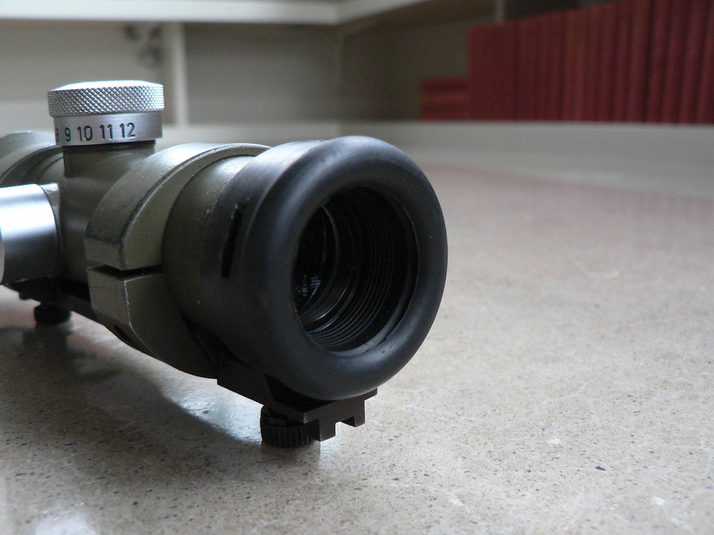
The third version, known as the "CETME LV", is what we will be looking at here. The CETME LV was intended to be used as a marksman's rifle and had a STANAG scope mount permanently welded to the receiver. Only a very few of this version (145) are being built by MarColMar.
SO...who is MarColMar? Well, rather than get it wrong, I'll just quote their website:
"MarColMar Firearms is an FFL / SOT / and Class II Manufacturer that specializes in bringing important historical military firearms back to life - for both collectors and shooters. Founded by Dave Bane in Richmond Indiana in 2007, MarColMar has been committed to merging modern manufacturing methods and materials, with surplus military parts, to recreate the most accurate, high quality, and reliable firearms available to the consumer market.
Our past projects and collaborations with other fine industry leaders, has resulted in some of the finest semi-auto firearm shooters and collectables, all of which have rapidly increased in demand and value – such as the Semi PKM, the Bulgarian AK-74, our milled Uk vz 59, and the UKM. Our latest project, the CETME L, will now expand our limited production – high quality philosophy - to a broader market, allowing many other enthusiasts to access our products and designs, and enjoy them for generations."
And here is a link to their site:
https://www.marcolmarfirearms.com/
Now, if it sounds to you like I'm advertising for MarColMar (I often use MCM for brevity) that's because I absolutely am. BUT I'm not advertising because they asked me to or because they are paying me to or because they are giving me free stuff. NOPE. I'm doing this of my own accord because I bought one of their CETME L's and was so absolutely Impressed with the Quality of their product, the Quality of their customer service and the Quality of who they are as people and a company that I feel compelled to get the word out about what kind of feast they are bringing to the firearm hobby's table. If you want to learn more about that, I again invite you to read the article I did earlier about the standard CETME L by typing the following into your favorite search engine:
MarColMar and HMG Cetme L a Detailed Comparison
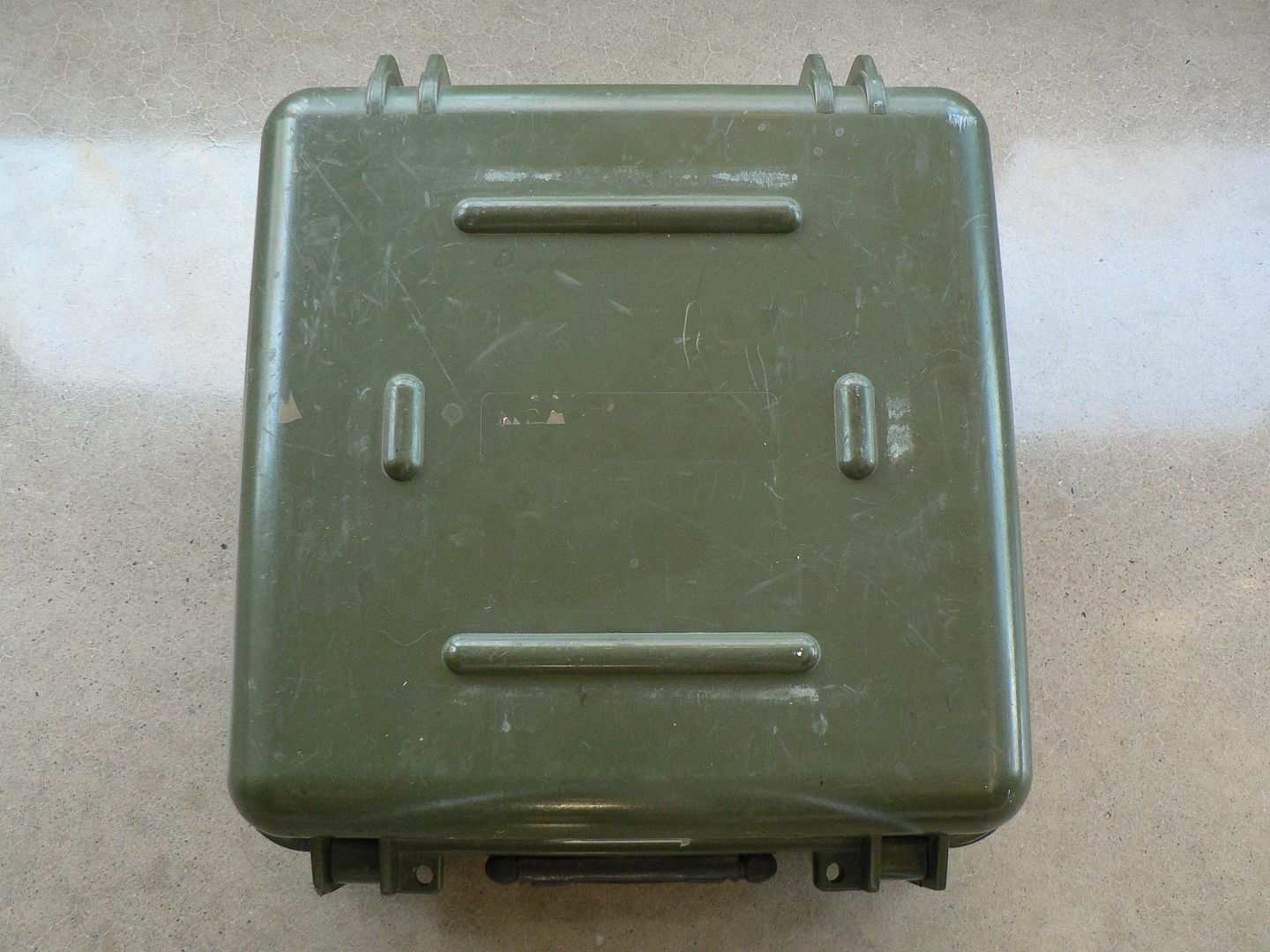
Have you read so much at this point that you're ready to go to sleep? Well wake up because it time to start looking at pictures. We'll start at the beginning.....the box:
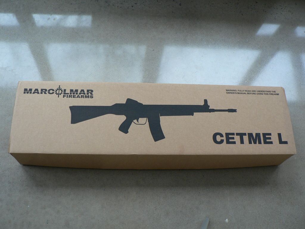
When your new rifle arrives, this is the first thing you'll see. There isn't much to say....it's a cardboard box. But it's a nice sturdy one.
On the end of the box, you'll find a sticker letting you know what's inside:
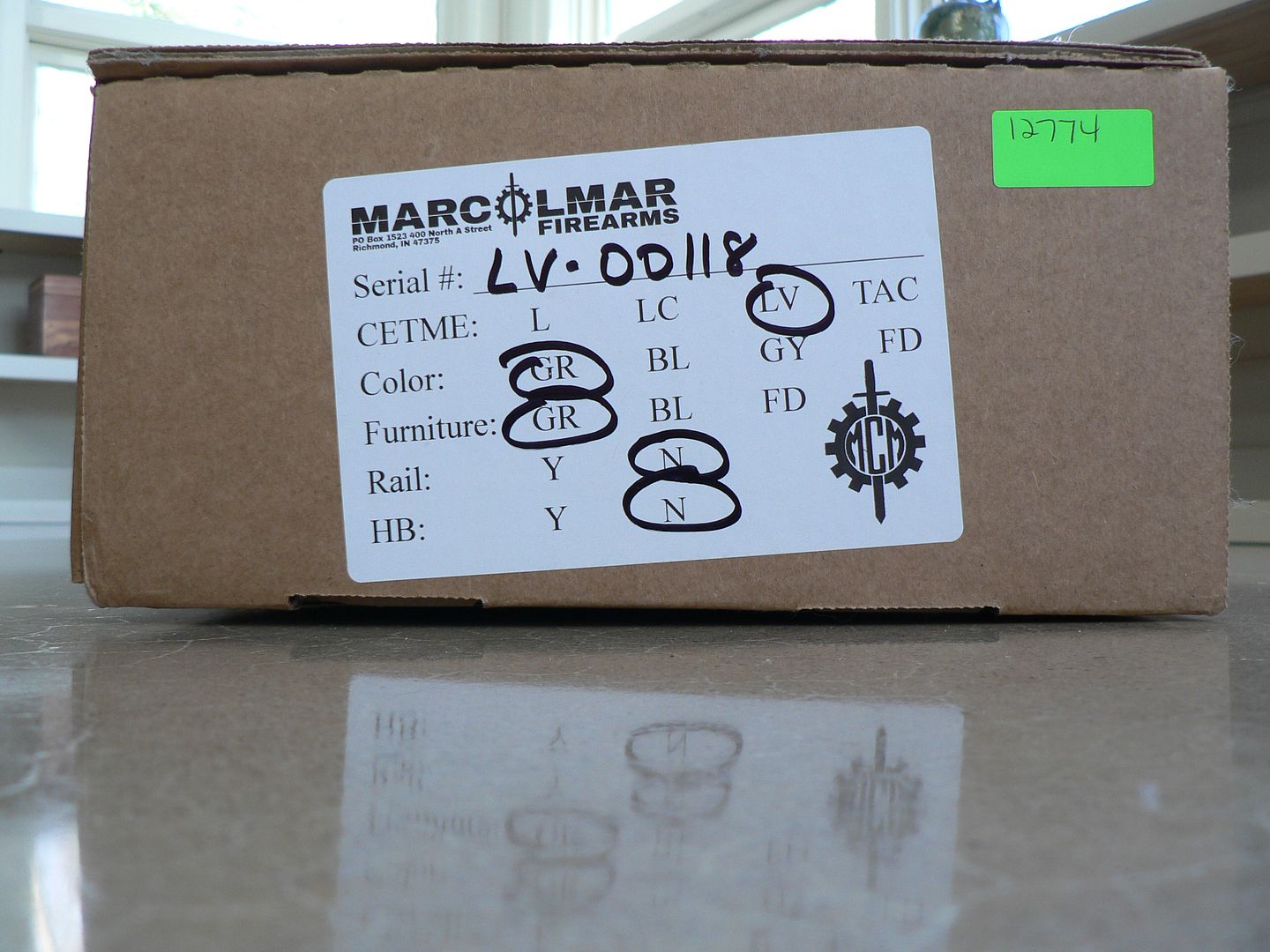
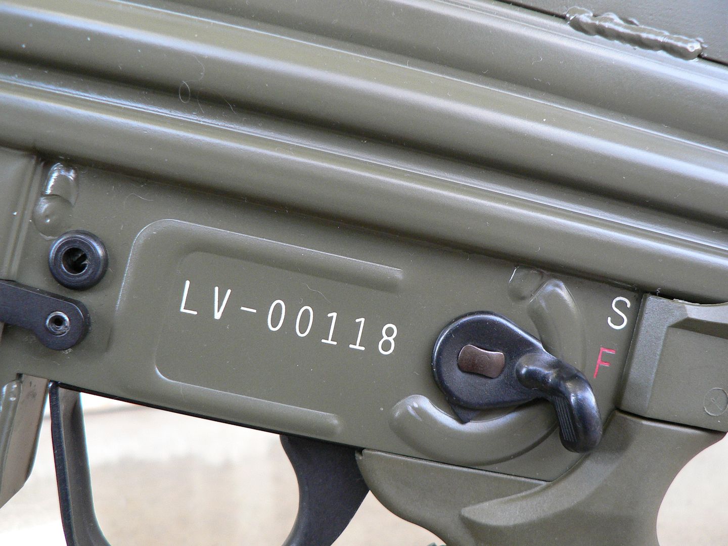
The Serial # line should be pretty obvious as to what it is.
The next line is the model. Notice that there is a fourth one (TAC) I haven't mentioned. That's because it isn't available yet. I'm pretty sure we all know what a "TAC" version will be though. Just know that such an animal, while I'm sure it will be the bomb, didn't originally exist. Tacticool is as American as apple pie!
Next is color. I chose green because that's the color they all were originally. But you can also order your rifle in Black, Grey or Flat Dark Earth.
Next is furniture. Again, I chose green because it's what would have originally been used in Spanish service. You can also order black or Flat Dark Earth.
The next line is marked "Rail". Since this rifle is custom designed to mount an optic already, that option is not available on this model. But if you choose to have one on either the L or LC model, MCM will ship your rifle with a perfectly aligned picatinny rail mounted on top the top of the receiver running from the front of the rear sight all the way to the front of the receiver.
The last line is marked "HB". You can specify either an original style pencil barrel or a larger circumference heavy barrel.
Upon opening the box, you'll find your new buddy well packed in form fitting high density foam:
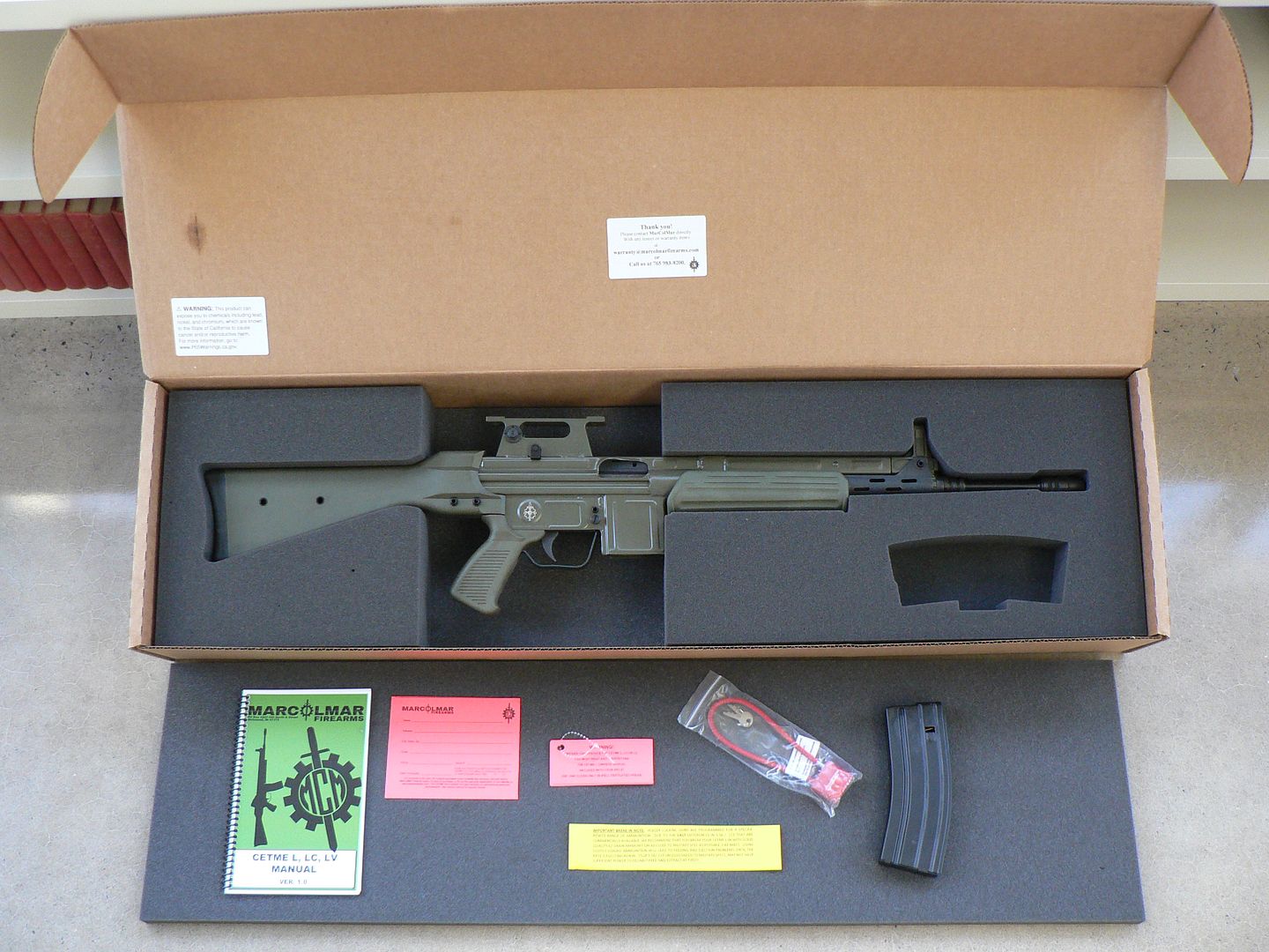
In addition to the rifle, you also find some other stuff which I have laid out for the picture. At the extreme left is the manual. We'll get a closer look at that in just a bit. Next to the manual we have a warranty card. Immediately to the right of that is a tag that was attached to the trigger guard informing you that you might shoot your eye out if you aren't careful. Below that are break-in directions. Continuing right, we have an action lock and, finally, at the extreme right is a standard US GI aluminum magazine made by Okay Industries.
The stickers inside the box top are contact information for MCM and another warning label. You can never have enough warning labels.
Here's a detail shot of the break-in information:
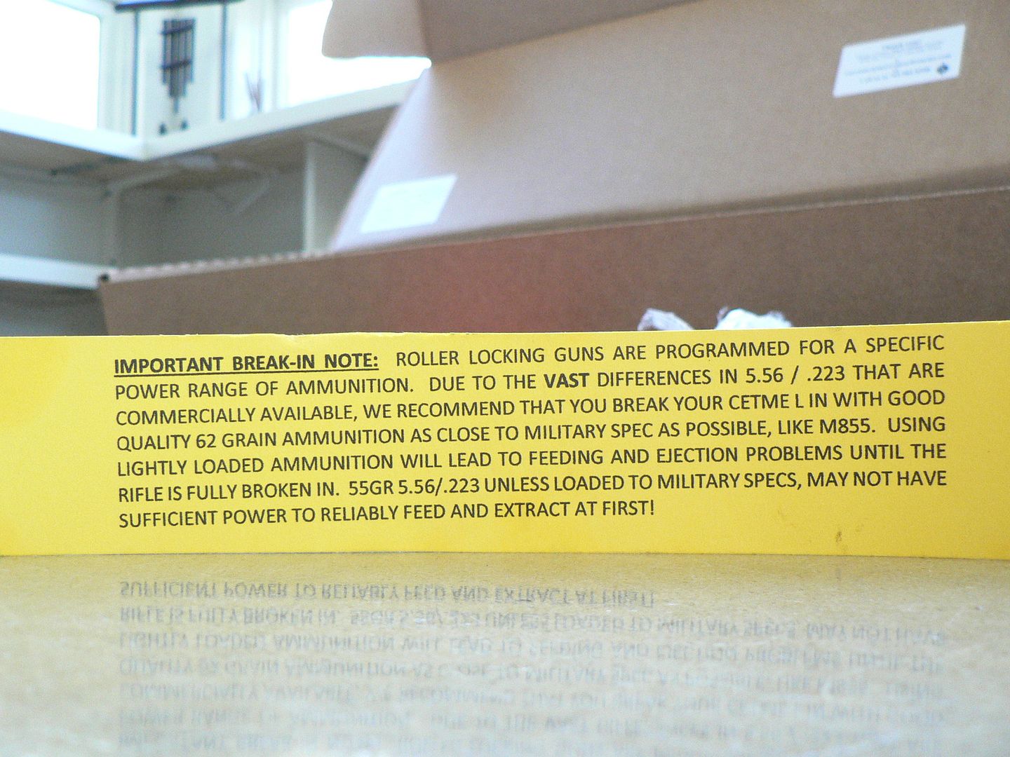
While I haven't shot this rifle yet, I have shot my L model quite a bit since purchasing it in early 2019 and it has yet to give me any problems. It's pretty much run like a Singer sewing machine since day one.
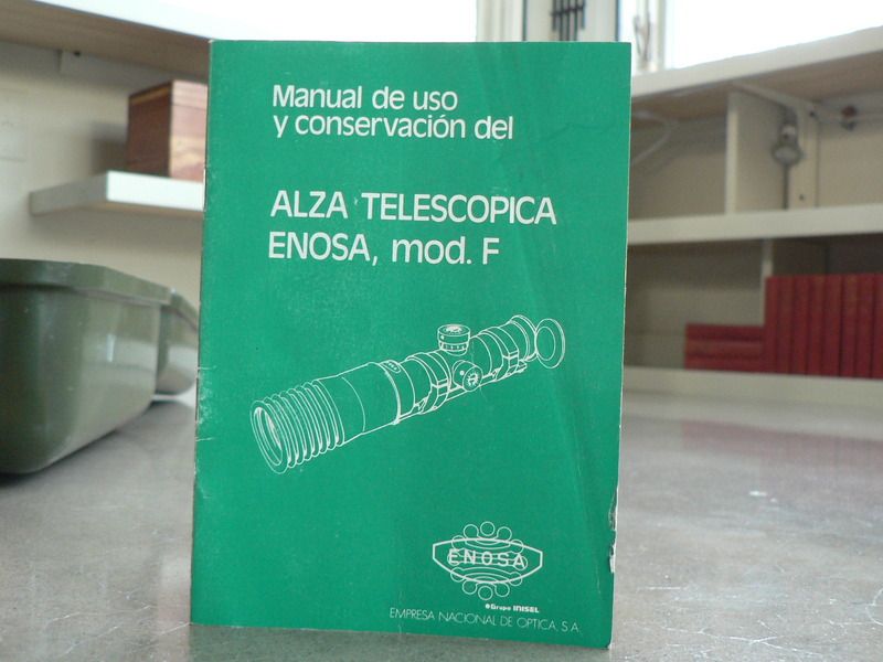
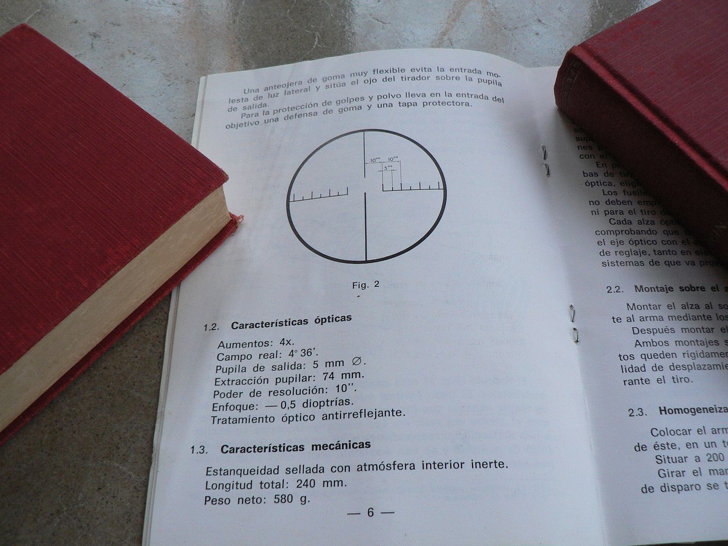
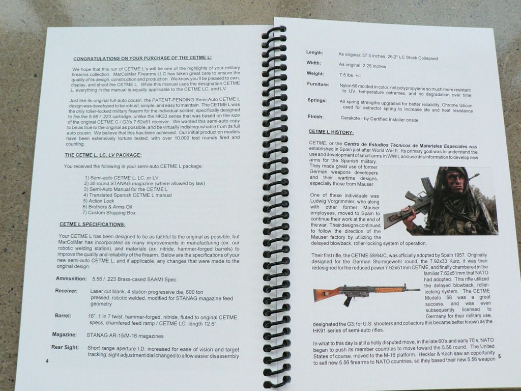
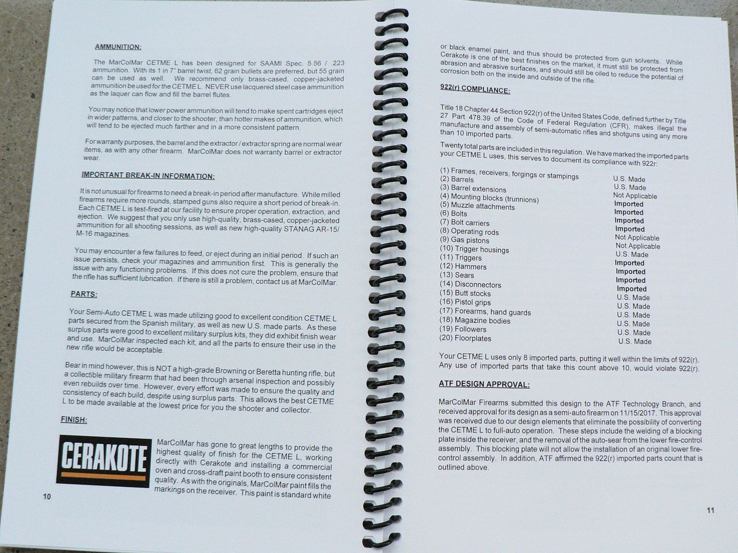
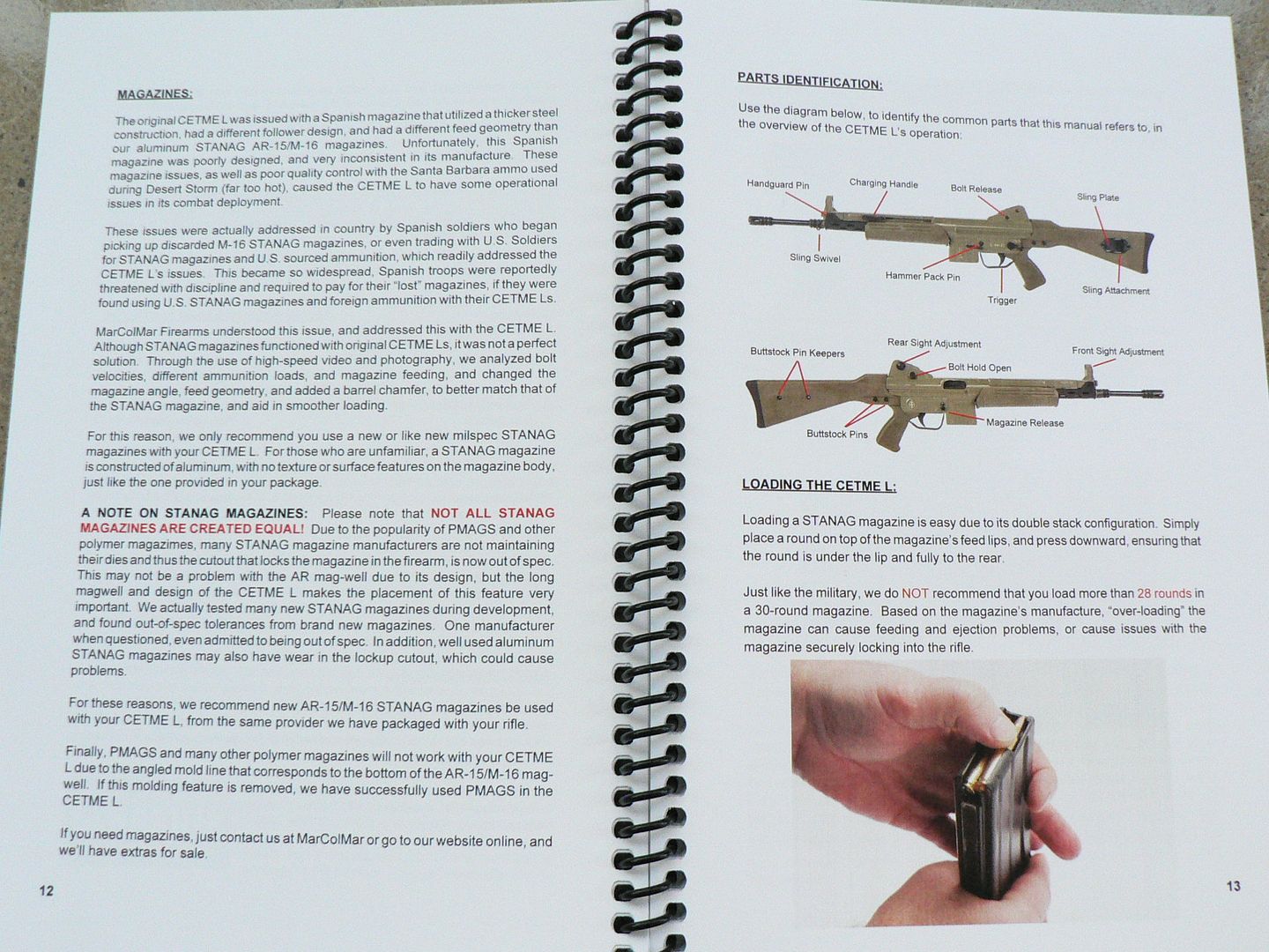
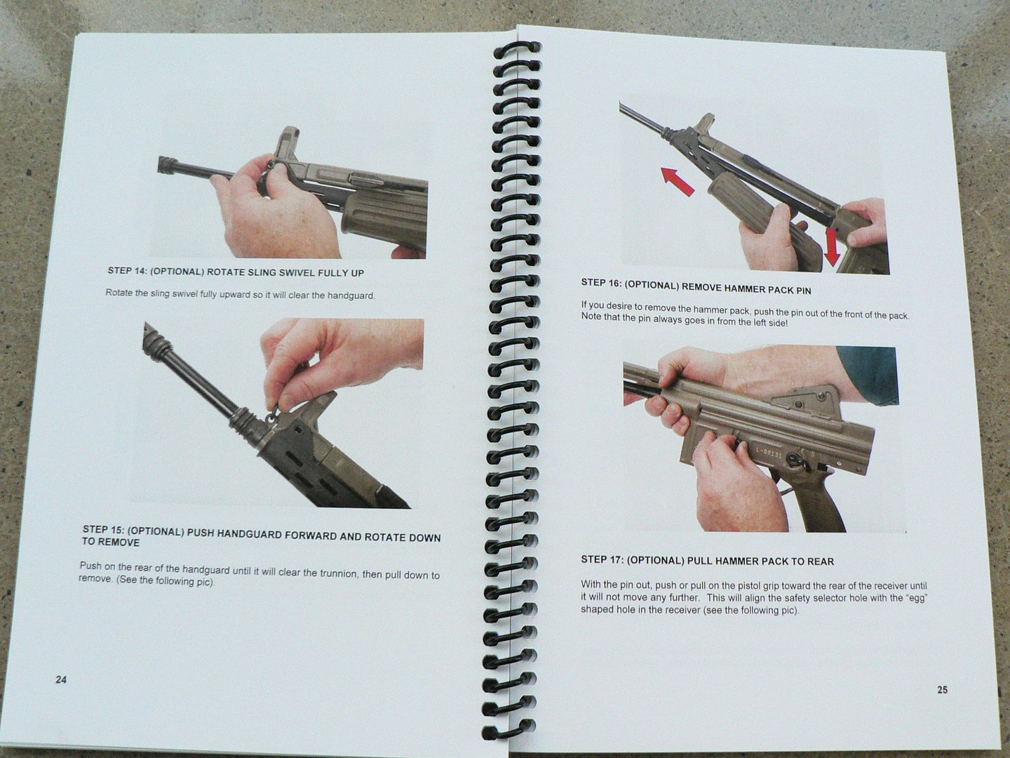
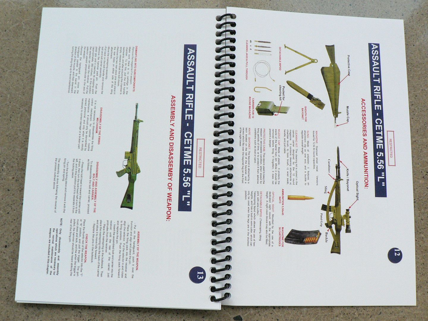
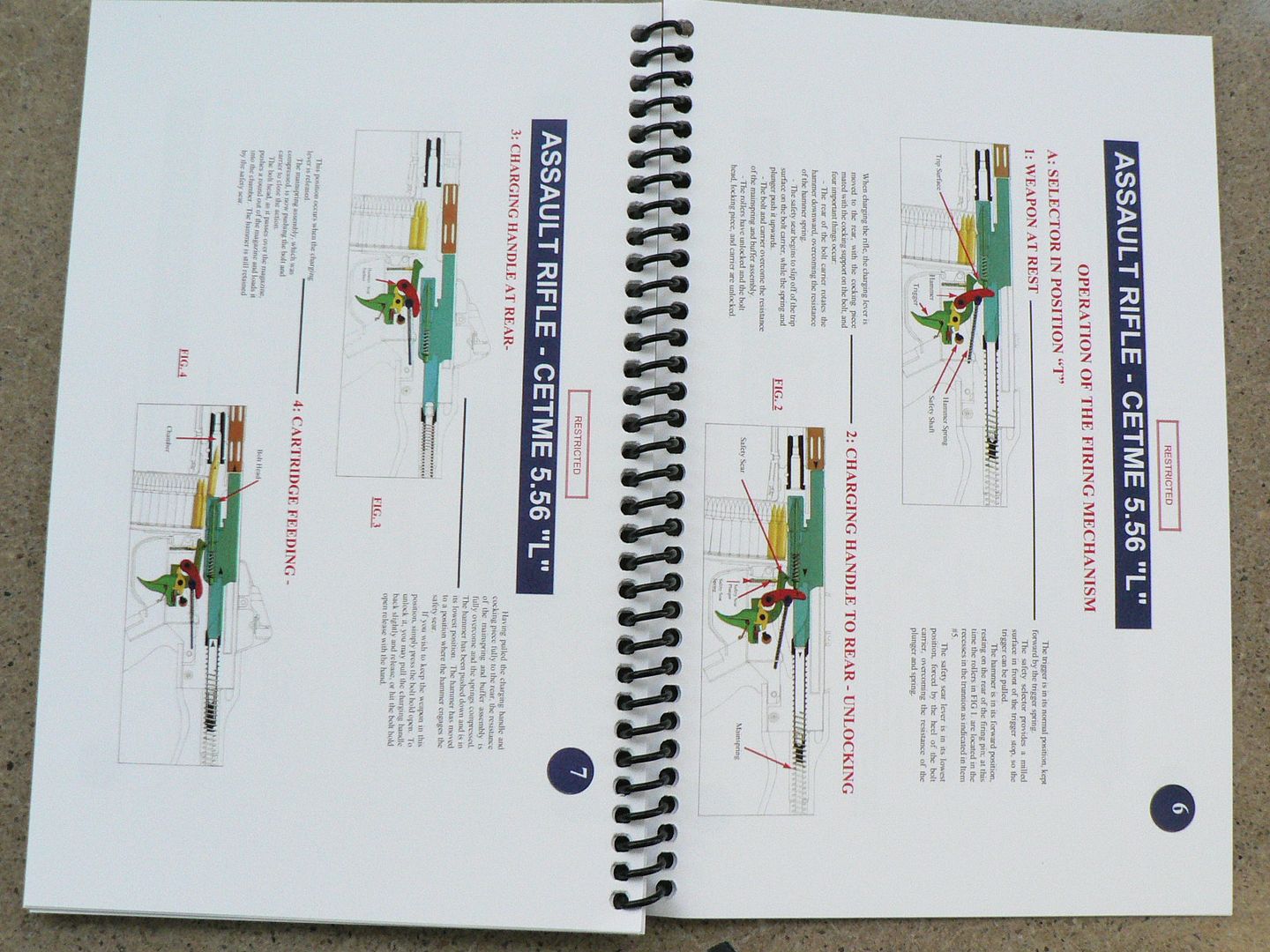
Let's take a closer look at the manual. I'm not going to post every page but trust me, it's well done. It's actually two manuals in one. The first half was done by MCM and covers some really interesting stuff. Besides the usual how to disassemble and how to clean sections, there is one on the History of the original rifle and some really informative text about the production of this new AMG including which parts are new US made. The second half is an English translation of an original Spanish manual complete with lots of pretty color pictures.
Some examples of the MCM half:
Some examples of the translated Spanish half:
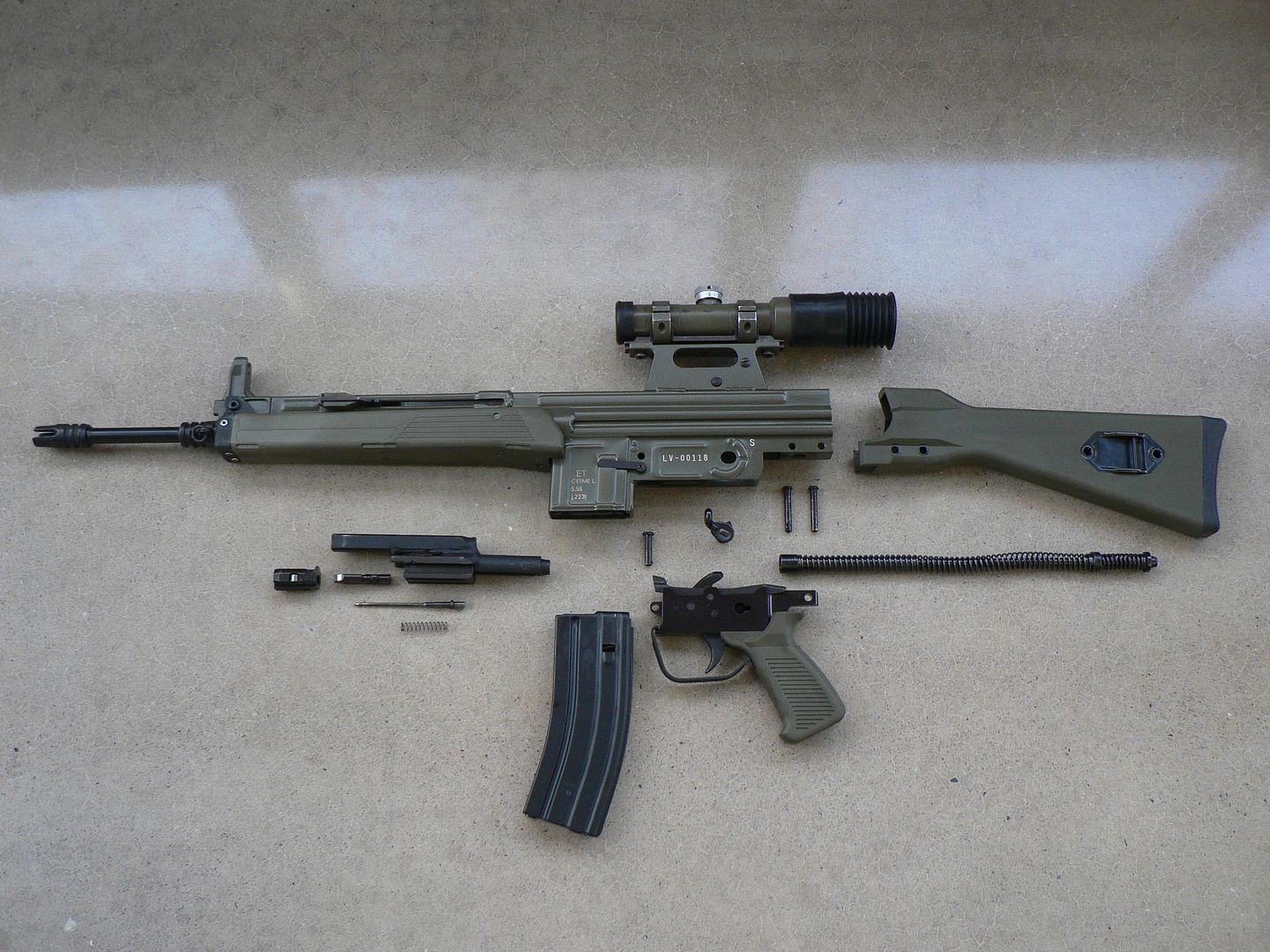
After checking out the extra stuff, it's time to take a look at the rifle. we'll start with a right side view:
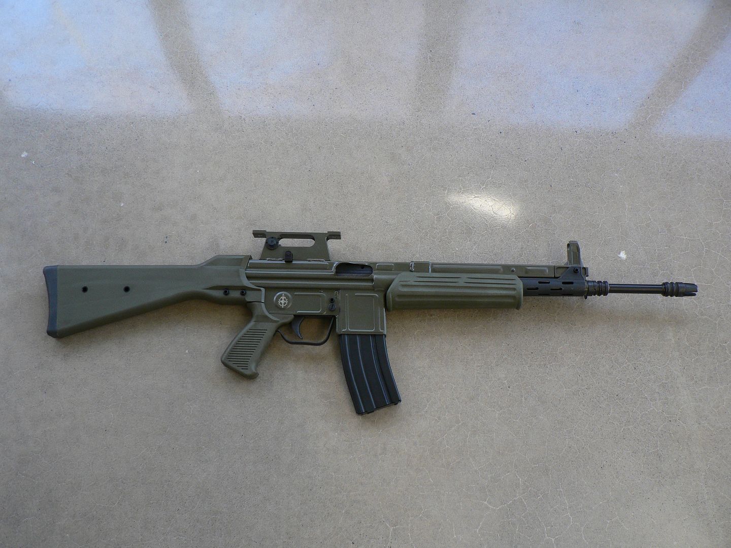
Yes, it looks weird without an optic on it but we'll see various different ones on there a little later. For now, I'm just showing it to you as it comes from MCM.
And the left side:
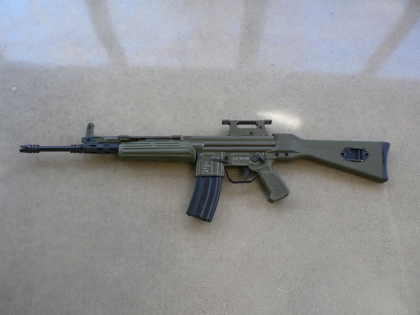
At this point we need to address what you are looking at. I mean, is this a kit build or a new made reproduction. Well, it's both really. If you refer to the pictures of the manual above, you'll see on page 11 just which parts are original Spanish and which are new made in the US. To paraphrase my earlier piece on the standard model:
"Simply putting a parts kit back together to make a legal functioning rifle was not good enough for MarColMar. They have built a reputation over the years for crafting what could essentially pass for a new firearm out of a decades old retired and torch cut pile of surplus parts. They only select the best parts kits to begin with. Then they carefully modify the design to make it an ATF compliant semi-auto while preserving the look and feel of the original. This includes in-depth testing and ongoing development until they are satisfied that the end product will look, feel and function at least as well as the original was intended to. While sorting through the kits and developing the prototypes, any components which do not meet their aesthetic or functional standards are reproduced using the best possible materials so that they are as good or better than original factory parts. Only once they have everything finalized and sourced do they move on to production. MCM feels it's far better to delay a release date in order to work all the bugs out of design and logistics than it is to release a flawed product on time. Production itself is done using the most modern methods (including a welding robot on the Cetme L, LC and LV) and materials. The end result is a firearm that looks and functions as good or better than the originals did decades ago. According to Dave Bane, that's always been their standard way of doing things and that's the standard they've held their new Cetme L/LC/LV's to as well."
The only caveat I would apply to the above quote is that the MCM rifle actually exceeds the original rifle in Quality of both build and function. When I originally wrote that, I hadn't actually held or fired an original example. That is no longer the case.
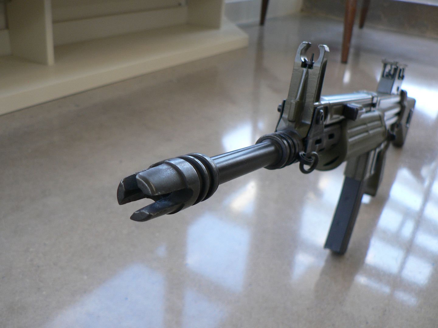
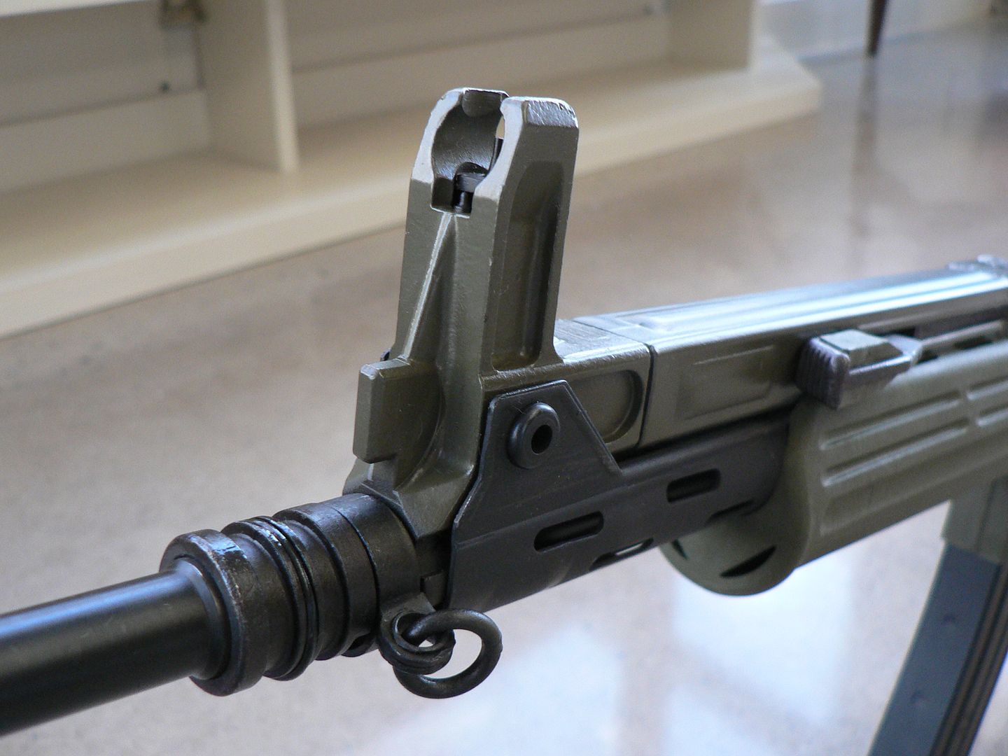
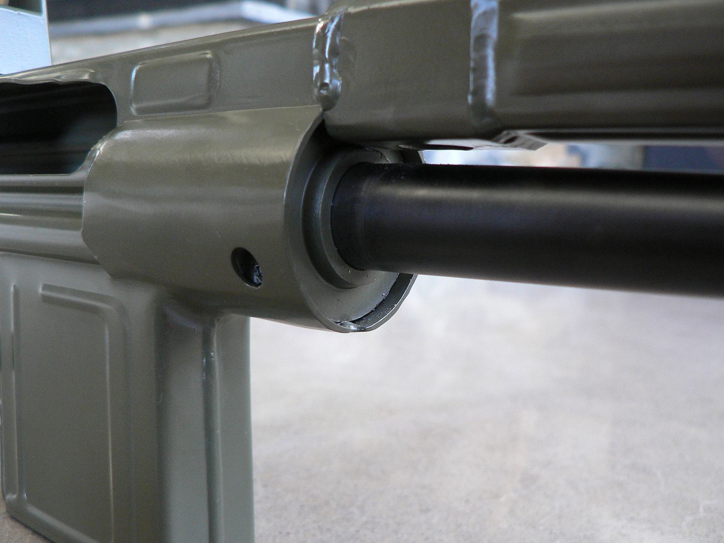
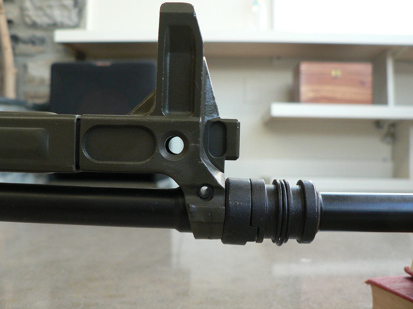
That's it for this post. In the next, we'll begin looking at details starting at the muzzle. I sincerely hope you check back to read some more and if you like it, please let me know. It's always nice to hear that someone enjoys the fruits of your labor. See you soon!
Fast forward until a few years ago when a little north of 10,000 5.56mm CETME rifles were removed from storage in Spain, scrapped and sold to the US market as parts kits. Of these, MarColMar ended up with approximately 10,000 kits in three versions. They are, from top to bottom, the LV, L and LC:
The vast majority of the kits were the standard fixed stock "L" version designed to be used primarily with iron sights and although many (but not all) did have a rear sight tower capable of having a scope mount attached, the optic mount seems to be vanishingly rare at this point. If you have one, please let me know as I'd LOVE to document it. If you are interested in the standard "L" version rebuilt by MarColMar, I wrote about one of those in-depth earlier this year and compared it to both a Hill and Mac kit rebuild and an original intact Spanish specimen. Just type the following into your favorite search engine and you'll immediately find links to it on multiple sites:
MarColMar and HMG Cetme L a Detailed Comparison
Also acquired by were some of the "LC" version. The primary difference of this version compared to the standard "L" model is a collapsible butt stock intended make it more compact for movement or stowage. Of the approximately 10,000 kits acquired by MarColMar, only 645 were of this variety. If you are interested in reading about the LC, I encourage you to read the article I've just recently written about this version. It can easily be found on this very forum by searching "MarColMar CETME LC (Carbine) In Detail". I enjoyed writing it and I hope you enjoy reading it if you are so inclined.
The third version, known as the "CETME LV", is what we will be looking at here. The CETME LV was intended to be used as a marksman's rifle and had a STANAG scope mount permanently welded to the receiver. Only a very few of this version (145) are being built by MarColMar.
SO...who is MarColMar? Well, rather than get it wrong, I'll just quote their website:
"MarColMar Firearms is an FFL / SOT / and Class II Manufacturer that specializes in bringing important historical military firearms back to life - for both collectors and shooters. Founded by Dave Bane in Richmond Indiana in 2007, MarColMar has been committed to merging modern manufacturing methods and materials, with surplus military parts, to recreate the most accurate, high quality, and reliable firearms available to the consumer market.
Our past projects and collaborations with other fine industry leaders, has resulted in some of the finest semi-auto firearm shooters and collectables, all of which have rapidly increased in demand and value – such as the Semi PKM, the Bulgarian AK-74, our milled Uk vz 59, and the UKM. Our latest project, the CETME L, will now expand our limited production – high quality philosophy - to a broader market, allowing many other enthusiasts to access our products and designs, and enjoy them for generations."
And here is a link to their site:
https://www.marcolmarfirearms.com/
Now, if it sounds to you like I'm advertising for MarColMar (I often use MCM for brevity) that's because I absolutely am. BUT I'm not advertising because they asked me to or because they are paying me to or because they are giving me free stuff. NOPE. I'm doing this of my own accord because I bought one of their CETME L's and was so absolutely Impressed with the Quality of their product, the Quality of their customer service and the Quality of who they are as people and a company that I feel compelled to get the word out about what kind of feast they are bringing to the firearm hobby's table. If you want to learn more about that, I again invite you to read the article I did earlier about the standard CETME L by typing the following into your favorite search engine:
MarColMar and HMG Cetme L a Detailed Comparison
Have you read so much at this point that you're ready to go to sleep? Well wake up because it time to start looking at pictures. We'll start at the beginning.....the box:
When your new rifle arrives, this is the first thing you'll see. There isn't much to say....it's a cardboard box. But it's a nice sturdy one.
On the end of the box, you'll find a sticker letting you know what's inside:
The Serial # line should be pretty obvious as to what it is.
The next line is the model. Notice that there is a fourth one (TAC) I haven't mentioned. That's because it isn't available yet. I'm pretty sure we all know what a "TAC" version will be though. Just know that such an animal, while I'm sure it will be the bomb, didn't originally exist. Tacticool is as American as apple pie!
Next is color. I chose green because that's the color they all were originally. But you can also order your rifle in Black, Grey or Flat Dark Earth.
Next is furniture. Again, I chose green because it's what would have originally been used in Spanish service. You can also order black or Flat Dark Earth.
The next line is marked "Rail". Since this rifle is custom designed to mount an optic already, that option is not available on this model. But if you choose to have one on either the L or LC model, MCM will ship your rifle with a perfectly aligned picatinny rail mounted on top the top of the receiver running from the front of the rear sight all the way to the front of the receiver.
The last line is marked "HB". You can specify either an original style pencil barrel or a larger circumference heavy barrel.
Upon opening the box, you'll find your new buddy well packed in form fitting high density foam:
In addition to the rifle, you also find some other stuff which I have laid out for the picture. At the extreme left is the manual. We'll get a closer look at that in just a bit. Next to the manual we have a warranty card. Immediately to the right of that is a tag that was attached to the trigger guard informing you that you might shoot your eye out if you aren't careful. Below that are break-in directions. Continuing right, we have an action lock and, finally, at the extreme right is a standard US GI aluminum magazine made by Okay Industries.
The stickers inside the box top are contact information for MCM and another warning label. You can never have enough warning labels.
Here's a detail shot of the break-in information:
While I haven't shot this rifle yet, I have shot my L model quite a bit since purchasing it in early 2019 and it has yet to give me any problems. It's pretty much run like a Singer sewing machine since day one.
Let's take a closer look at the manual. I'm not going to post every page but trust me, it's well done. It's actually two manuals in one. The first half was done by MCM and covers some really interesting stuff. Besides the usual how to disassemble and how to clean sections, there is one on the History of the original rifle and some really informative text about the production of this new AMG including which parts are new US made. The second half is an English translation of an original Spanish manual complete with lots of pretty color pictures.
Some examples of the MCM half:


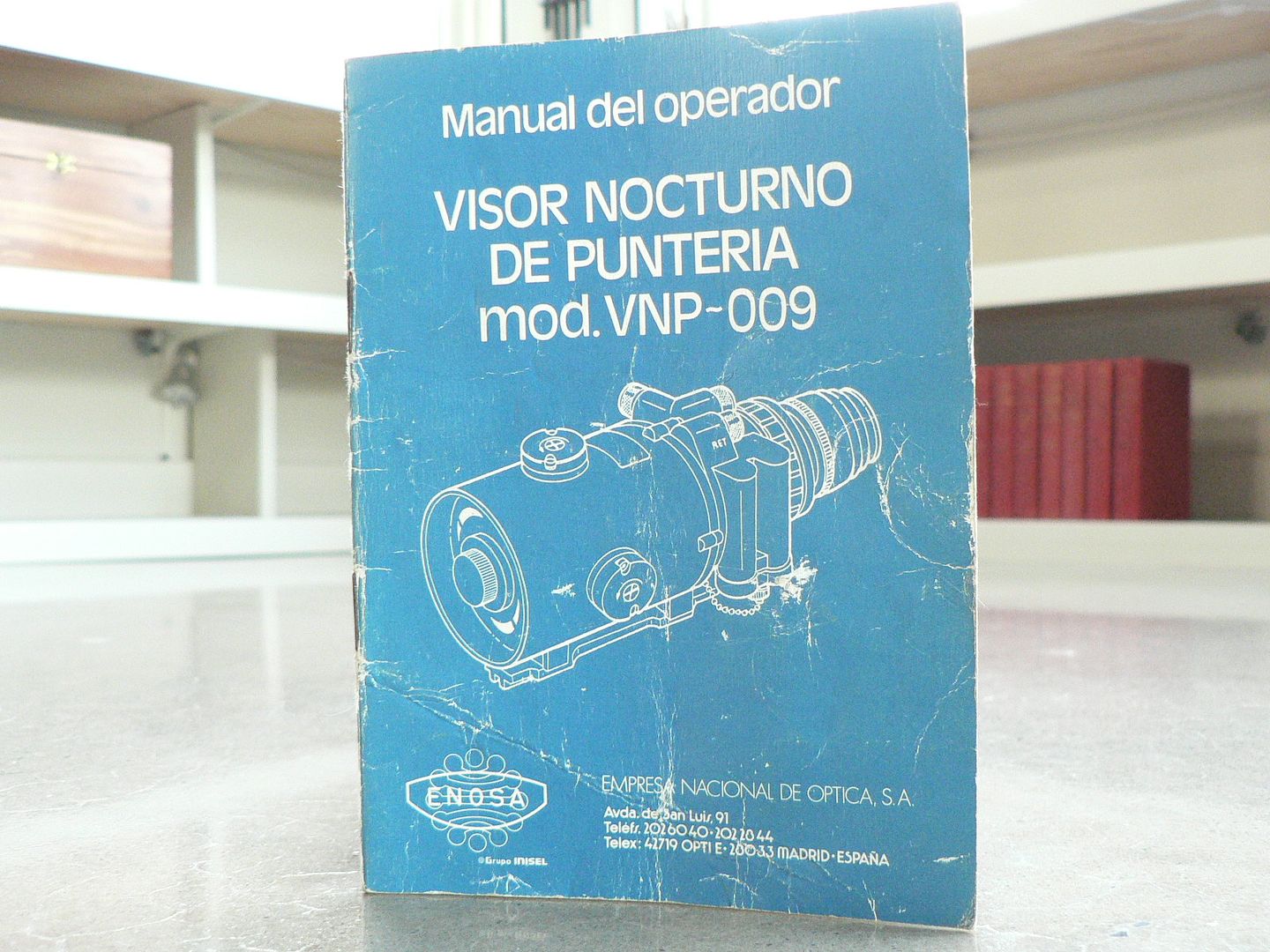
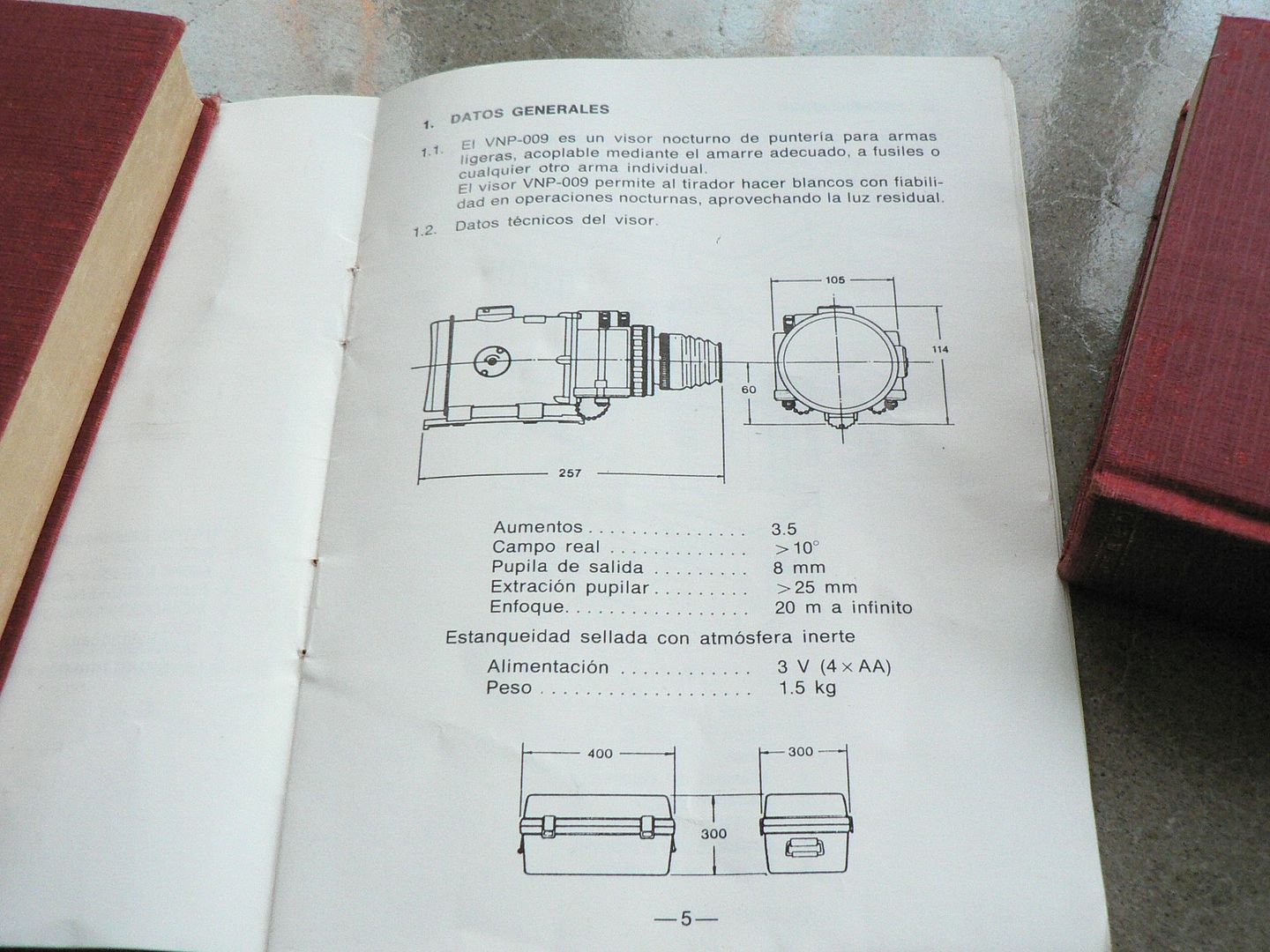
Some examples of the translated Spanish half:


After checking out the extra stuff, it's time to take a look at the rifle. we'll start with a right side view:
Yes, it looks weird without an optic on it but we'll see various different ones on there a little later. For now, I'm just showing it to you as it comes from MCM.
And the left side:
At this point we need to address what you are looking at. I mean, is this a kit build or a new made reproduction. Well, it's both really. If you refer to the pictures of the manual above, you'll see on page 11 just which parts are original Spanish and which are new made in the US. To paraphrase my earlier piece on the standard model:
"Simply putting a parts kit back together to make a legal functioning rifle was not good enough for MarColMar. They have built a reputation over the years for crafting what could essentially pass for a new firearm out of a decades old retired and torch cut pile of surplus parts. They only select the best parts kits to begin with. Then they carefully modify the design to make it an ATF compliant semi-auto while preserving the look and feel of the original. This includes in-depth testing and ongoing development until they are satisfied that the end product will look, feel and function at least as well as the original was intended to. While sorting through the kits and developing the prototypes, any components which do not meet their aesthetic or functional standards are reproduced using the best possible materials so that they are as good or better than original factory parts. Only once they have everything finalized and sourced do they move on to production. MCM feels it's far better to delay a release date in order to work all the bugs out of design and logistics than it is to release a flawed product on time. Production itself is done using the most modern methods (including a welding robot on the Cetme L, LC and LV) and materials. The end result is a firearm that looks and functions as good or better than the originals did decades ago. According to Dave Bane, that's always been their standard way of doing things and that's the standard they've held their new Cetme L/LC/LV's to as well."
The only caveat I would apply to the above quote is that the MCM rifle actually exceeds the original rifle in Quality of both build and function. When I originally wrote that, I hadn't actually held or fired an original example. That is no longer the case.
That's it for this post. In the next, we'll begin looking at details starting at the muzzle. I sincerely hope you check back to read some more and if you like it, please let me know. It's always nice to hear that someone enjoys the fruits of your labor. See you soon!
Last edited: