Combloc
Stop Negassing me!!!!!
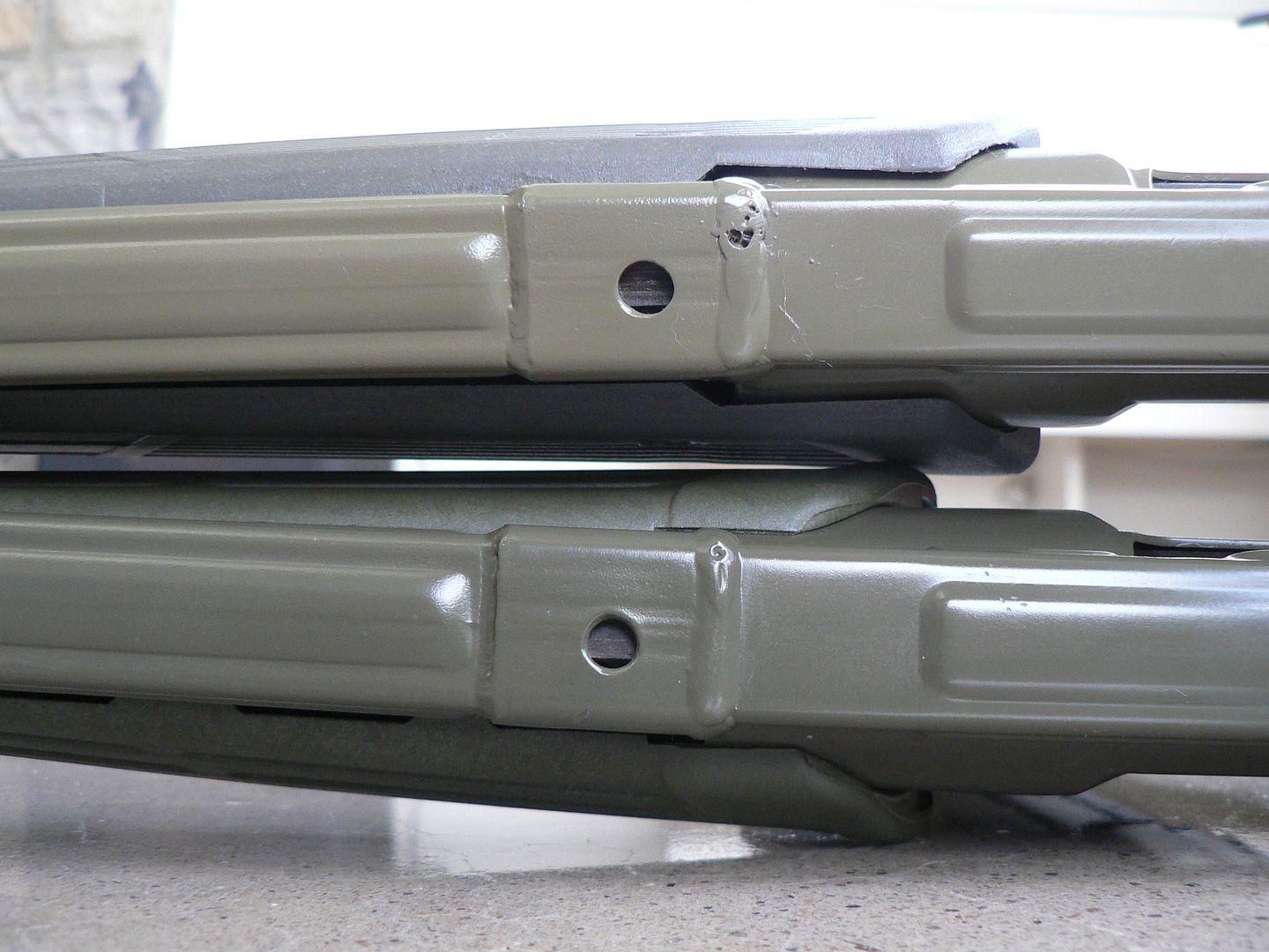
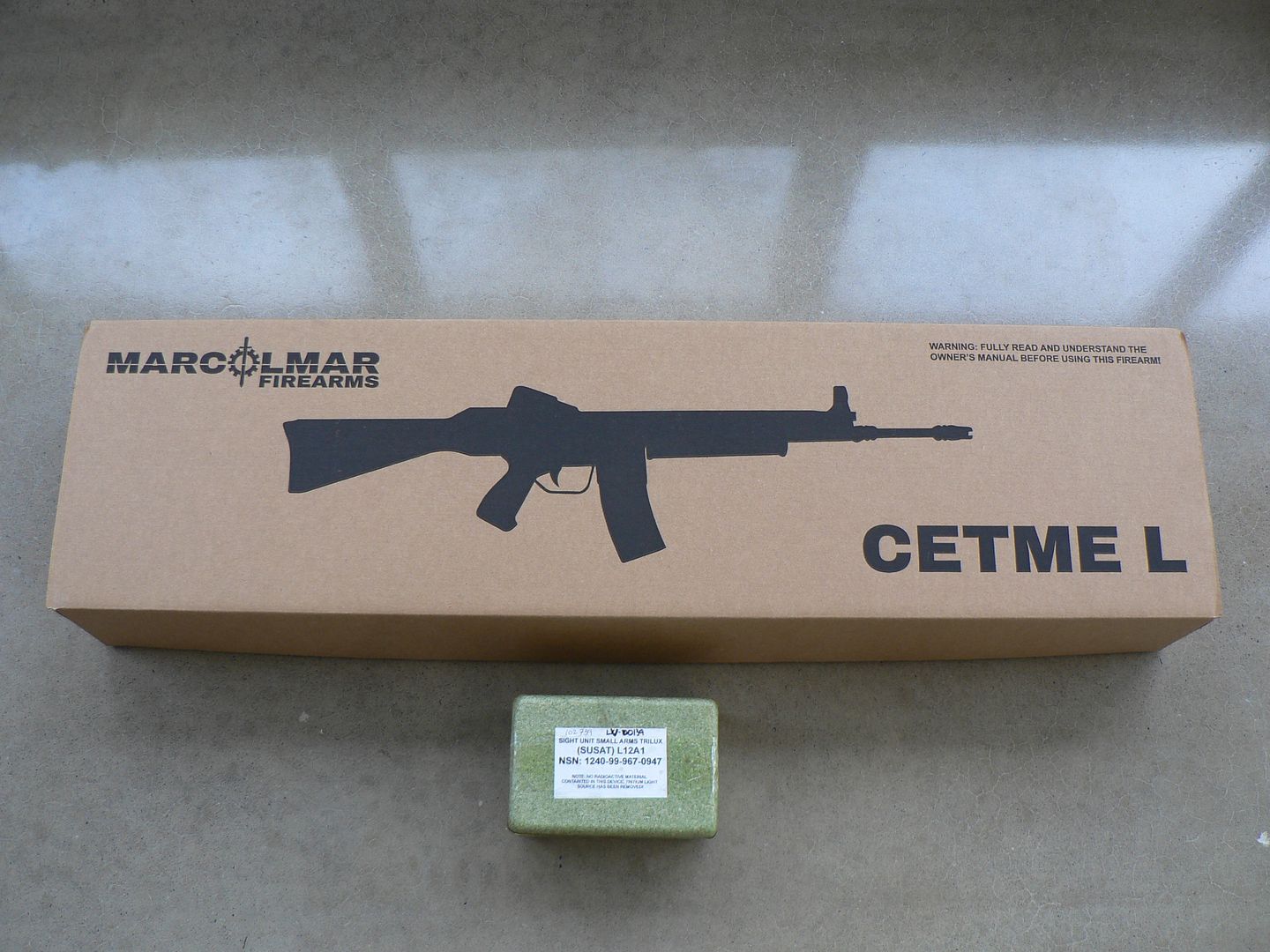
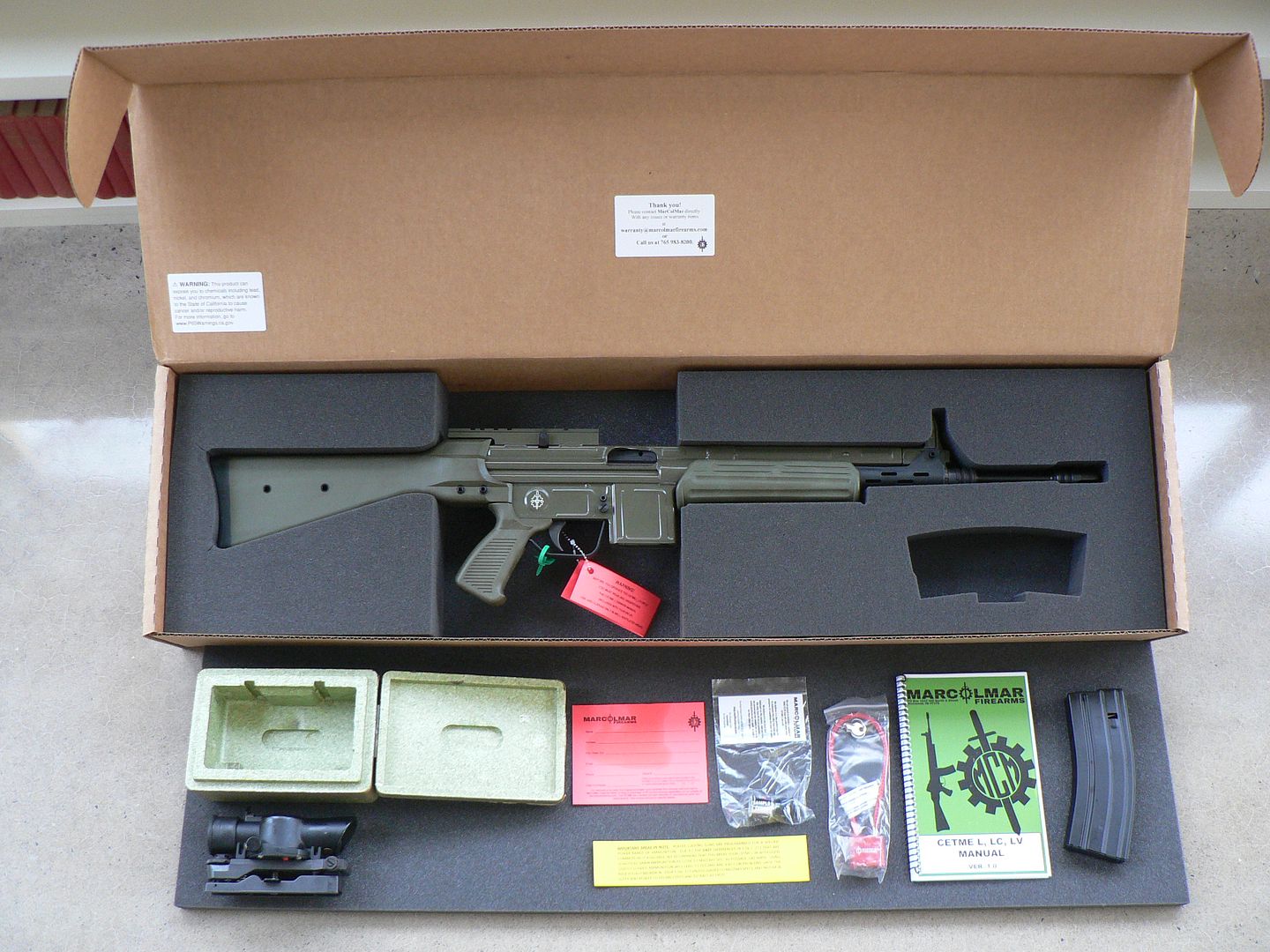
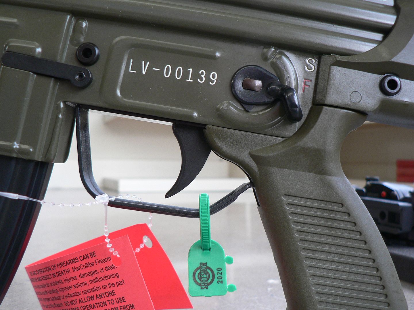
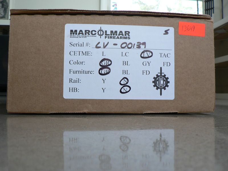
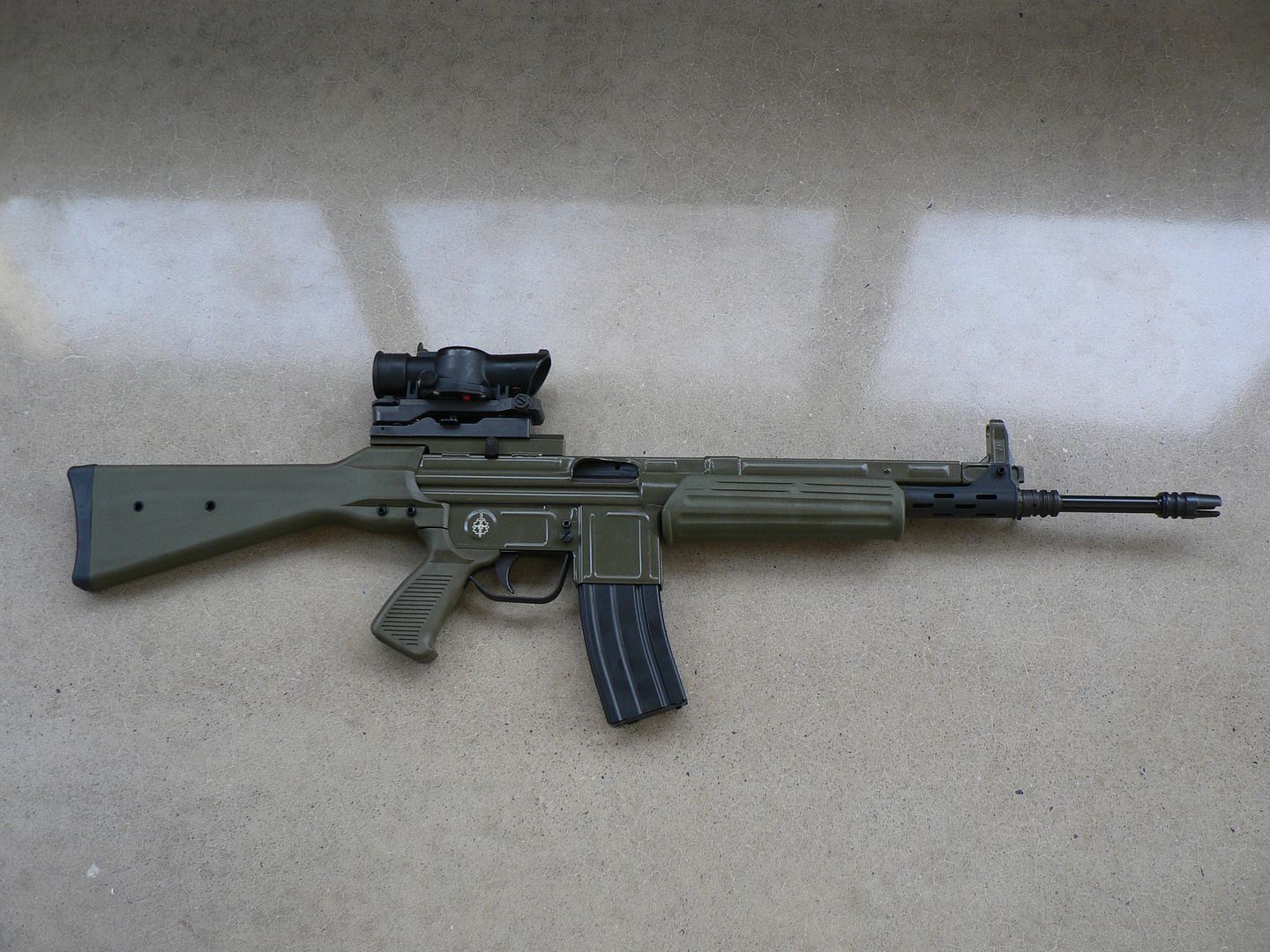
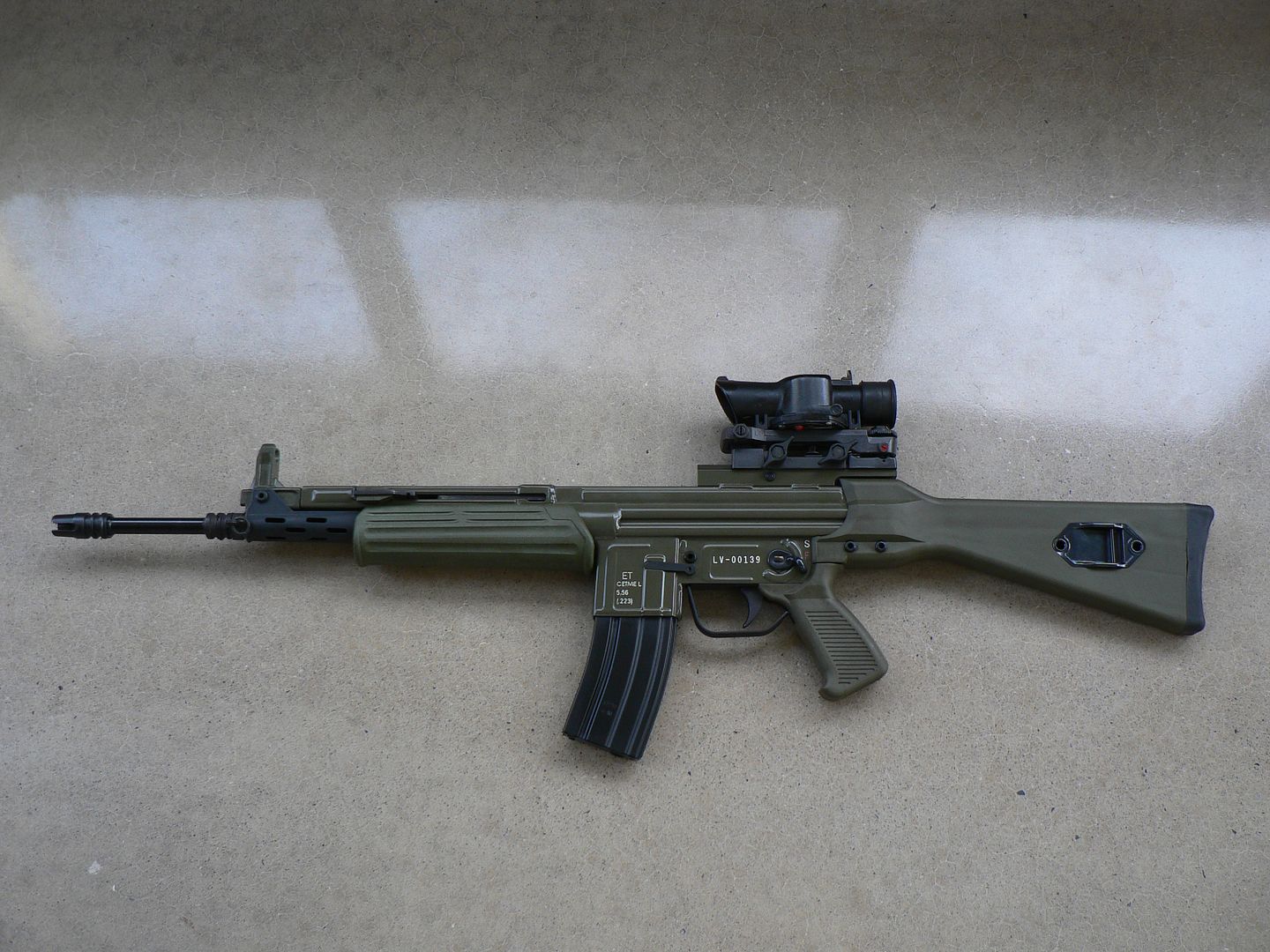
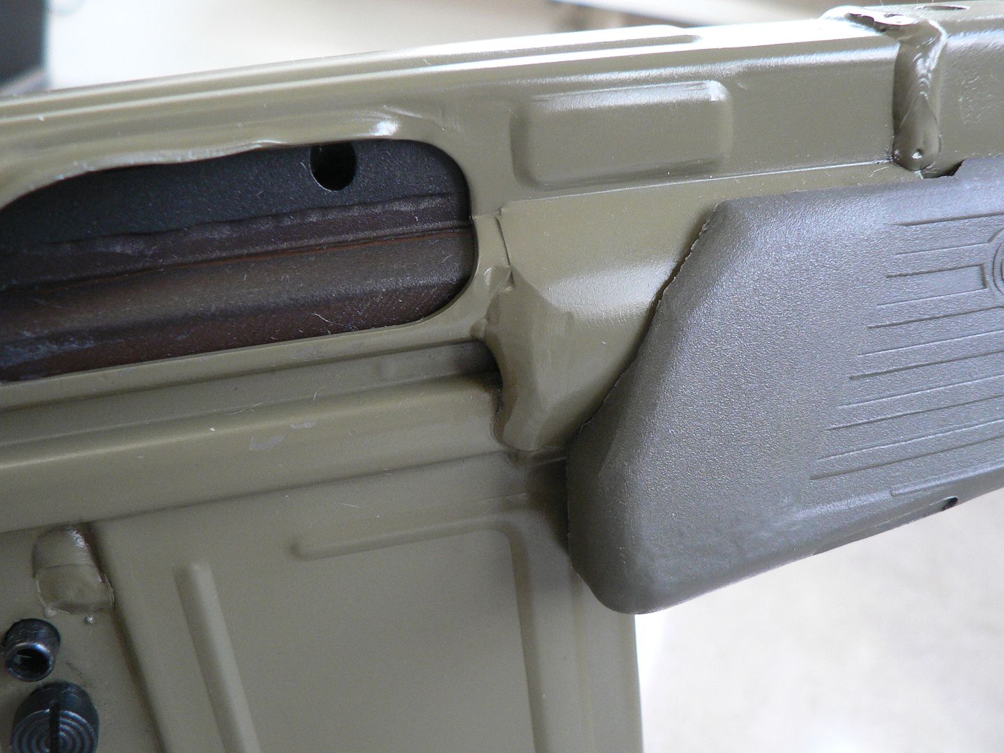
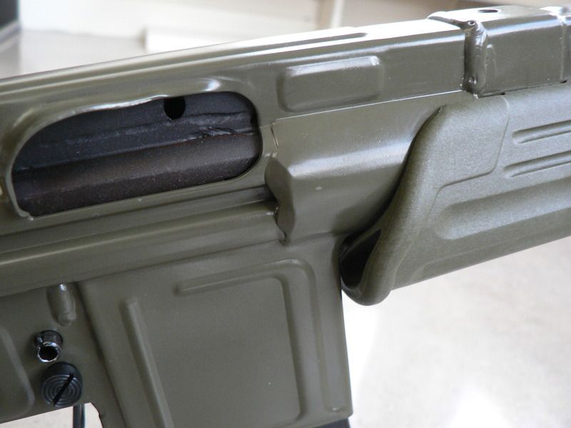
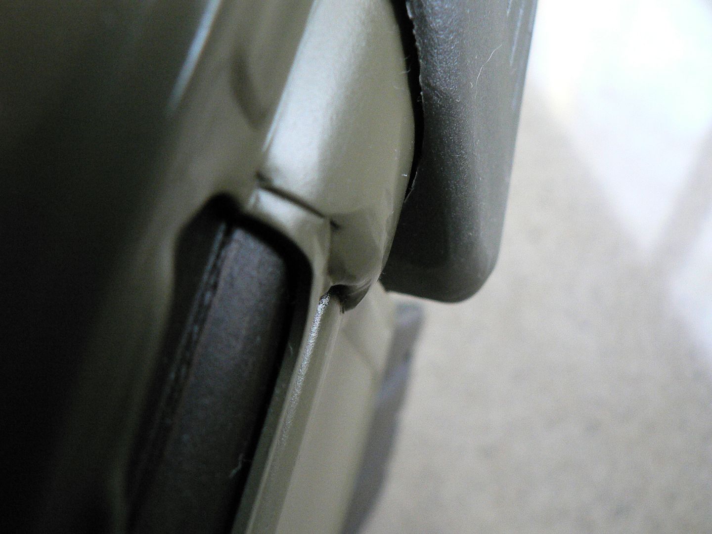
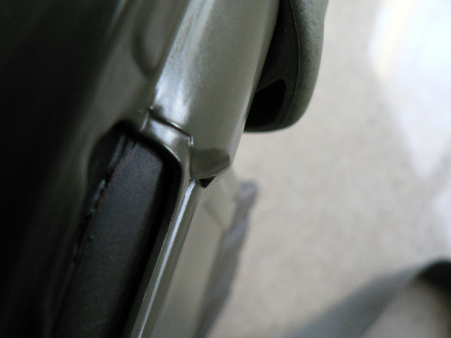
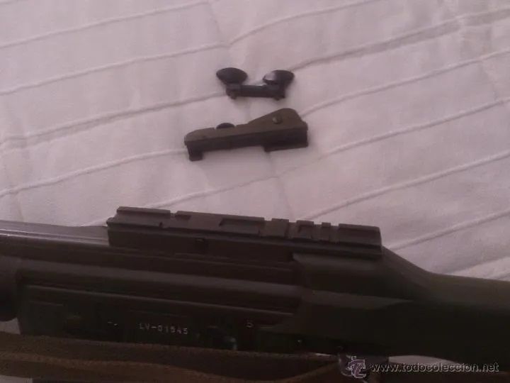
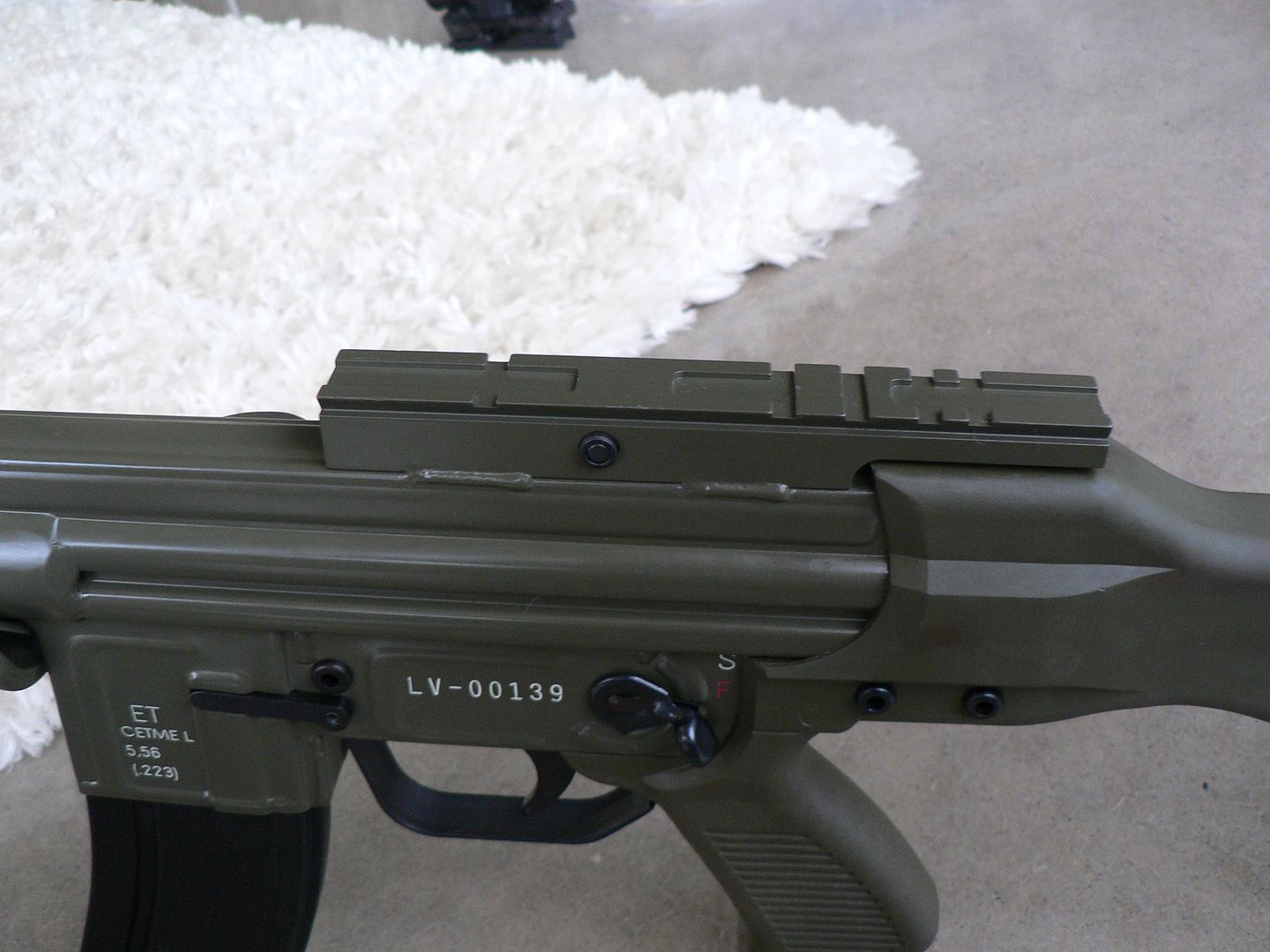
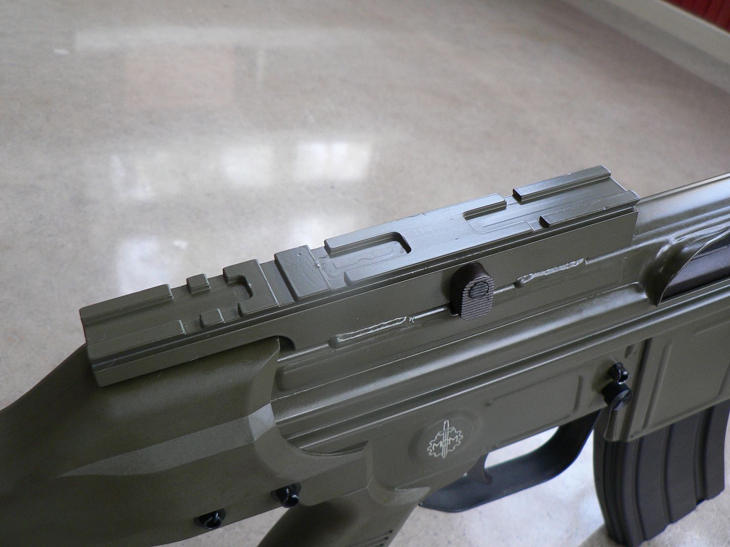
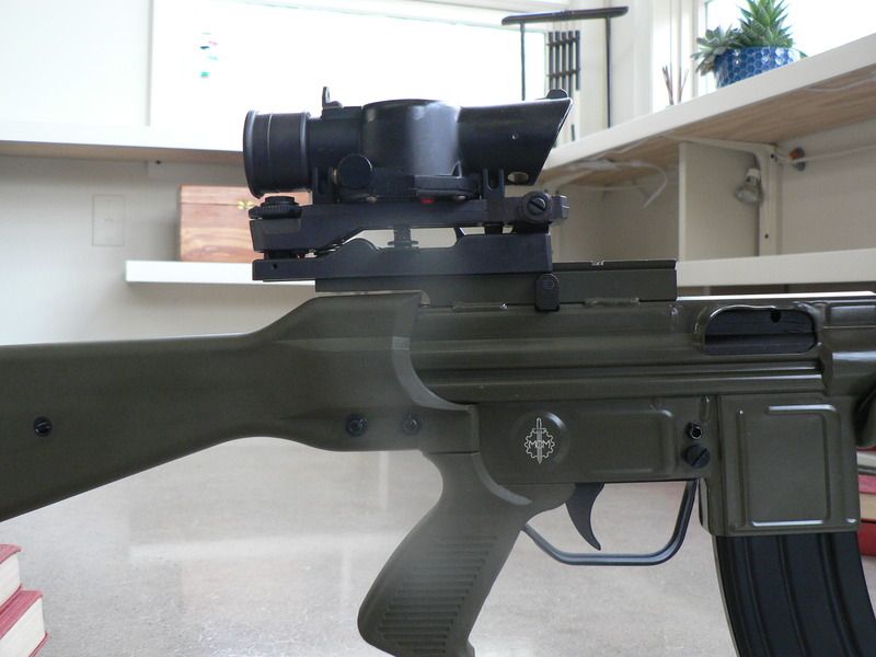
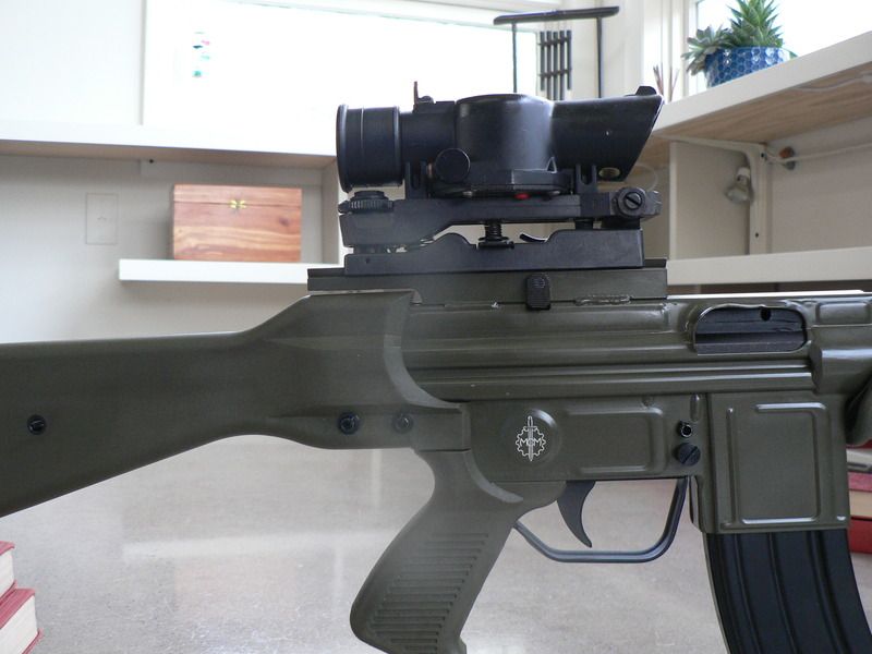
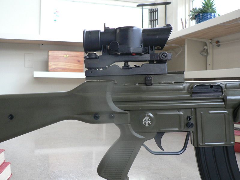
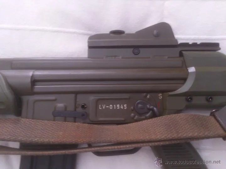
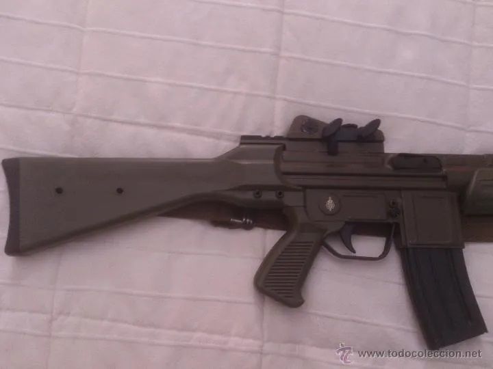
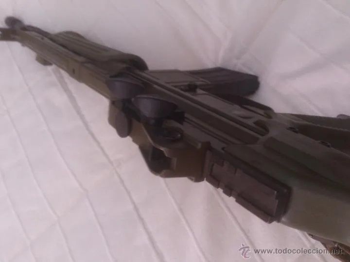
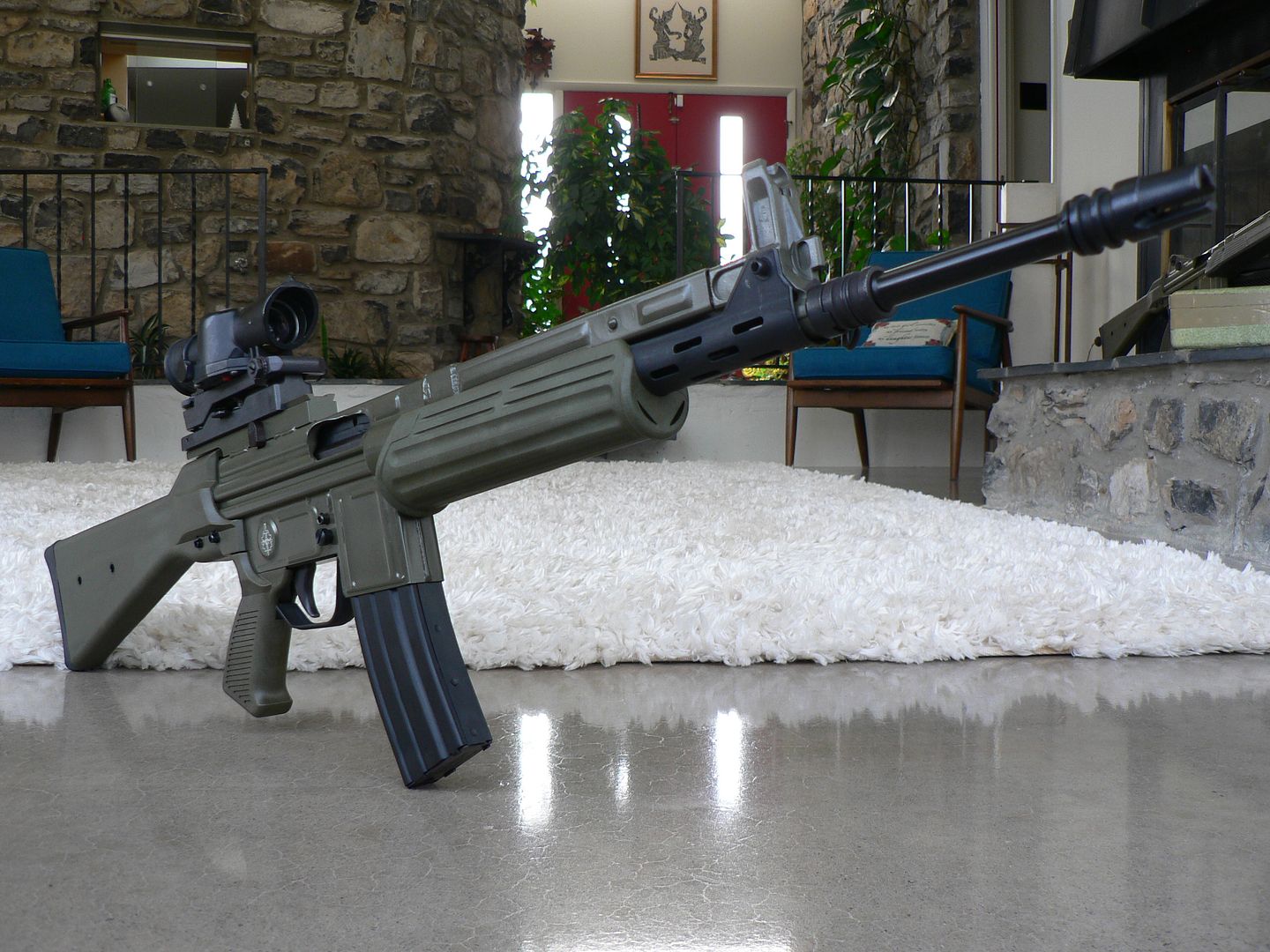
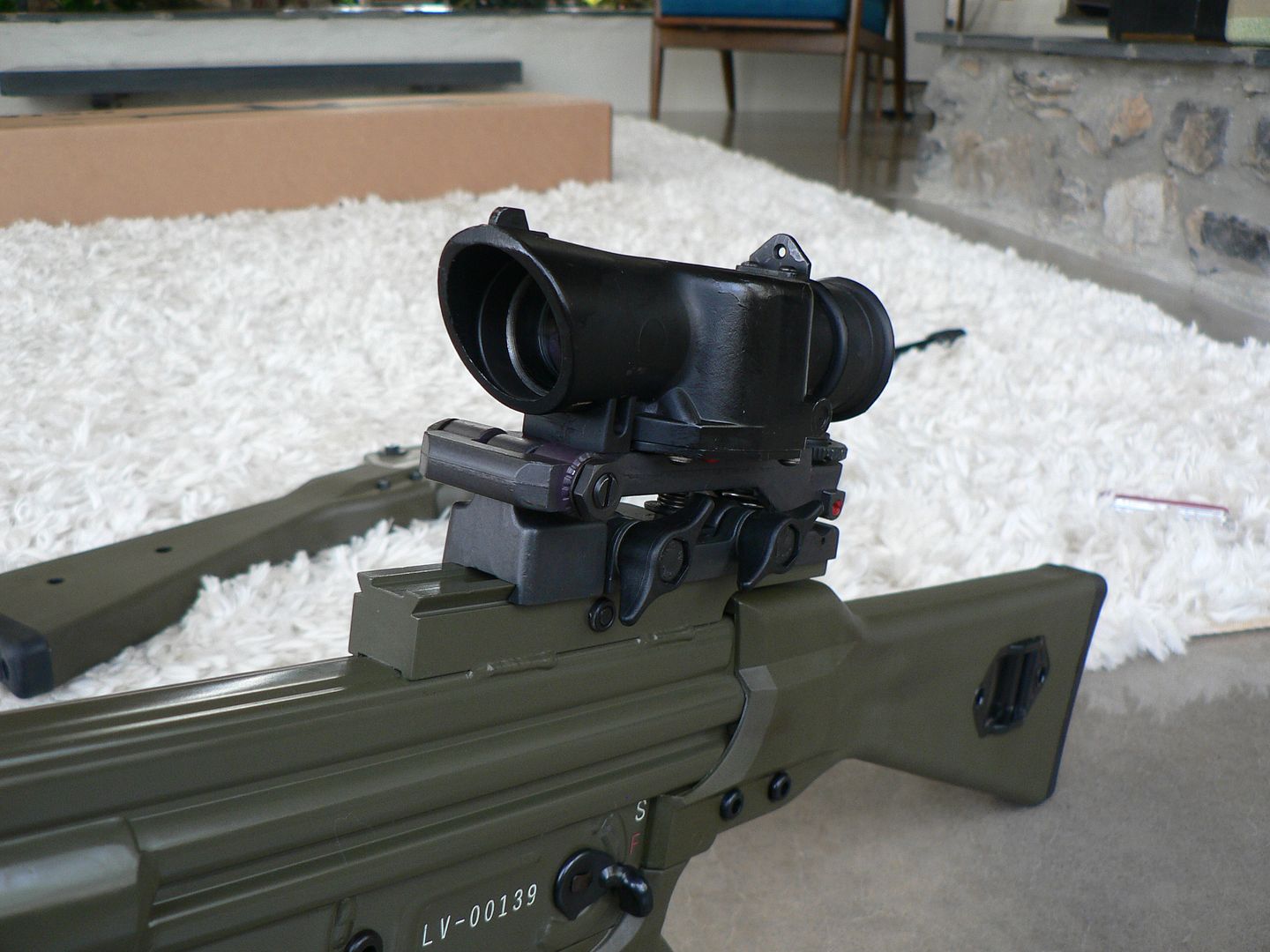
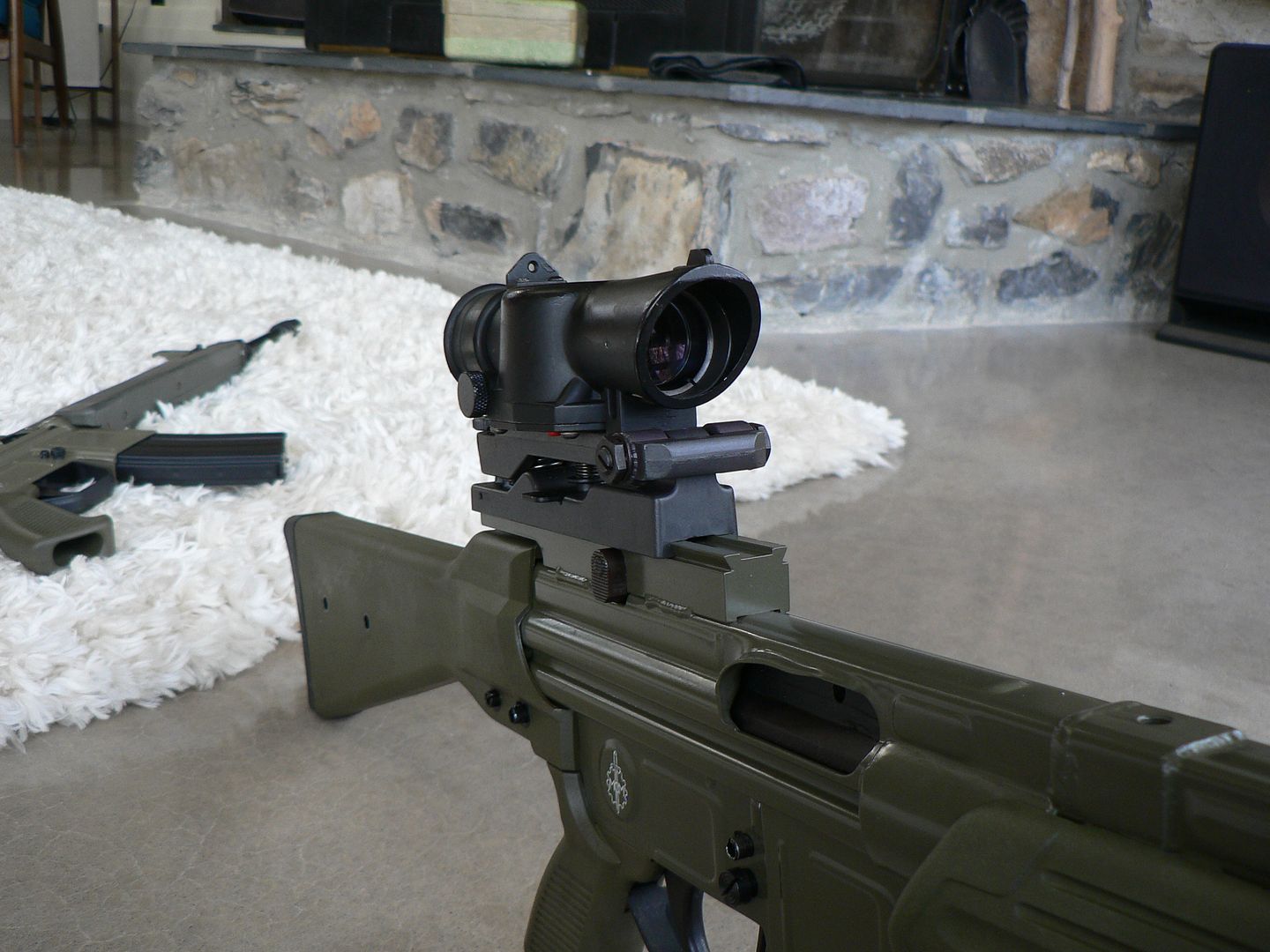
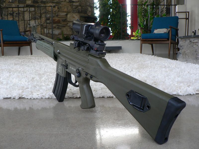
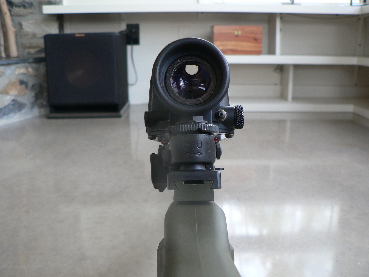
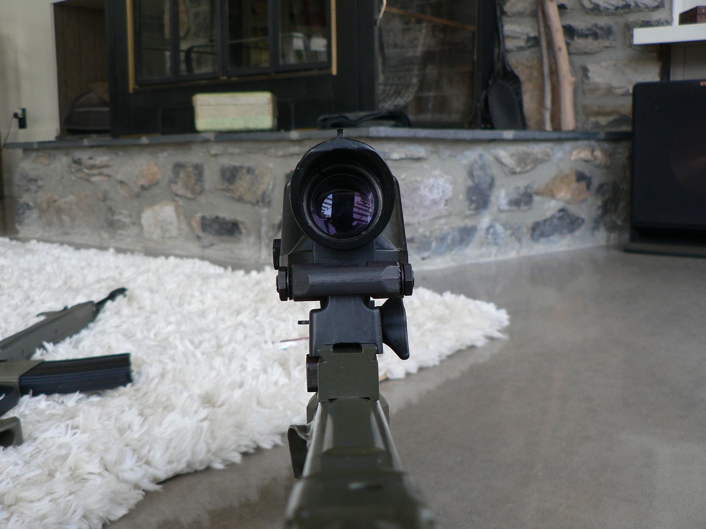
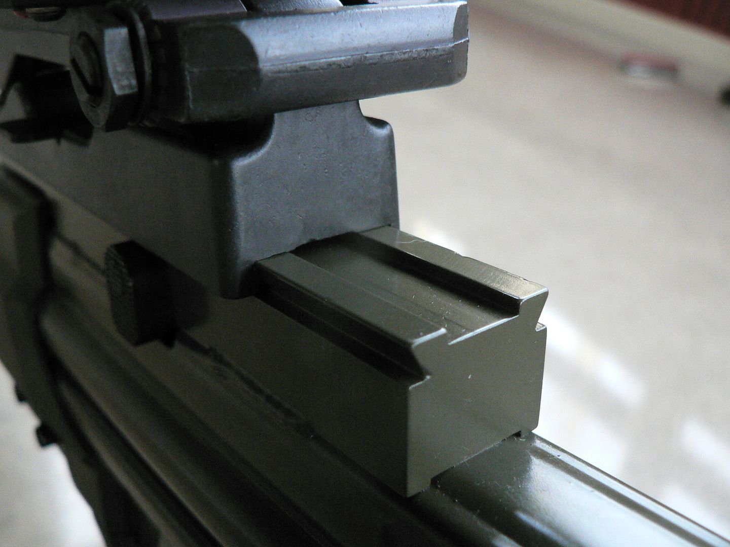
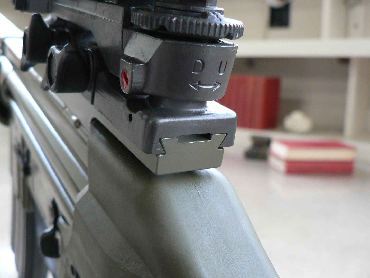
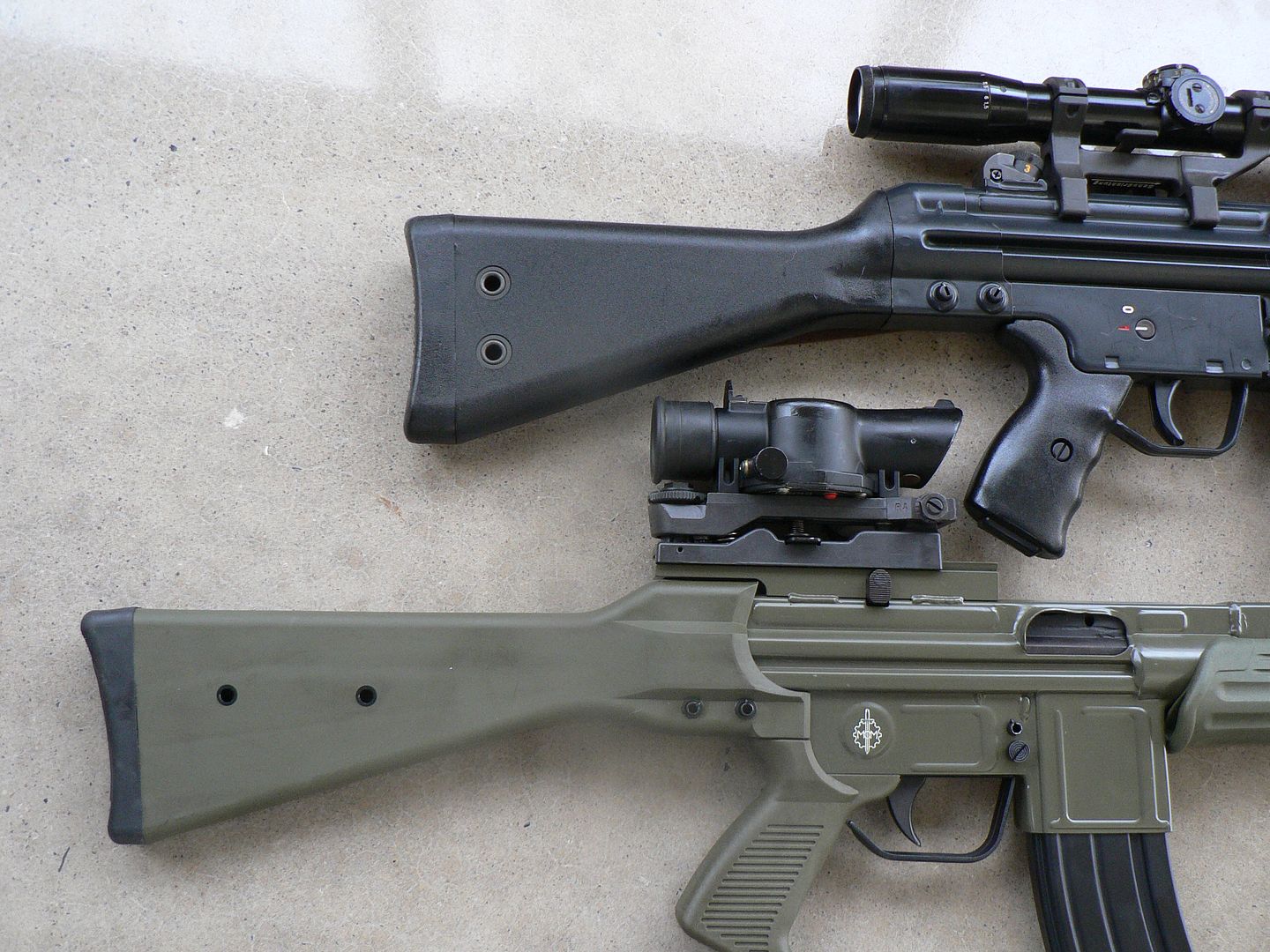
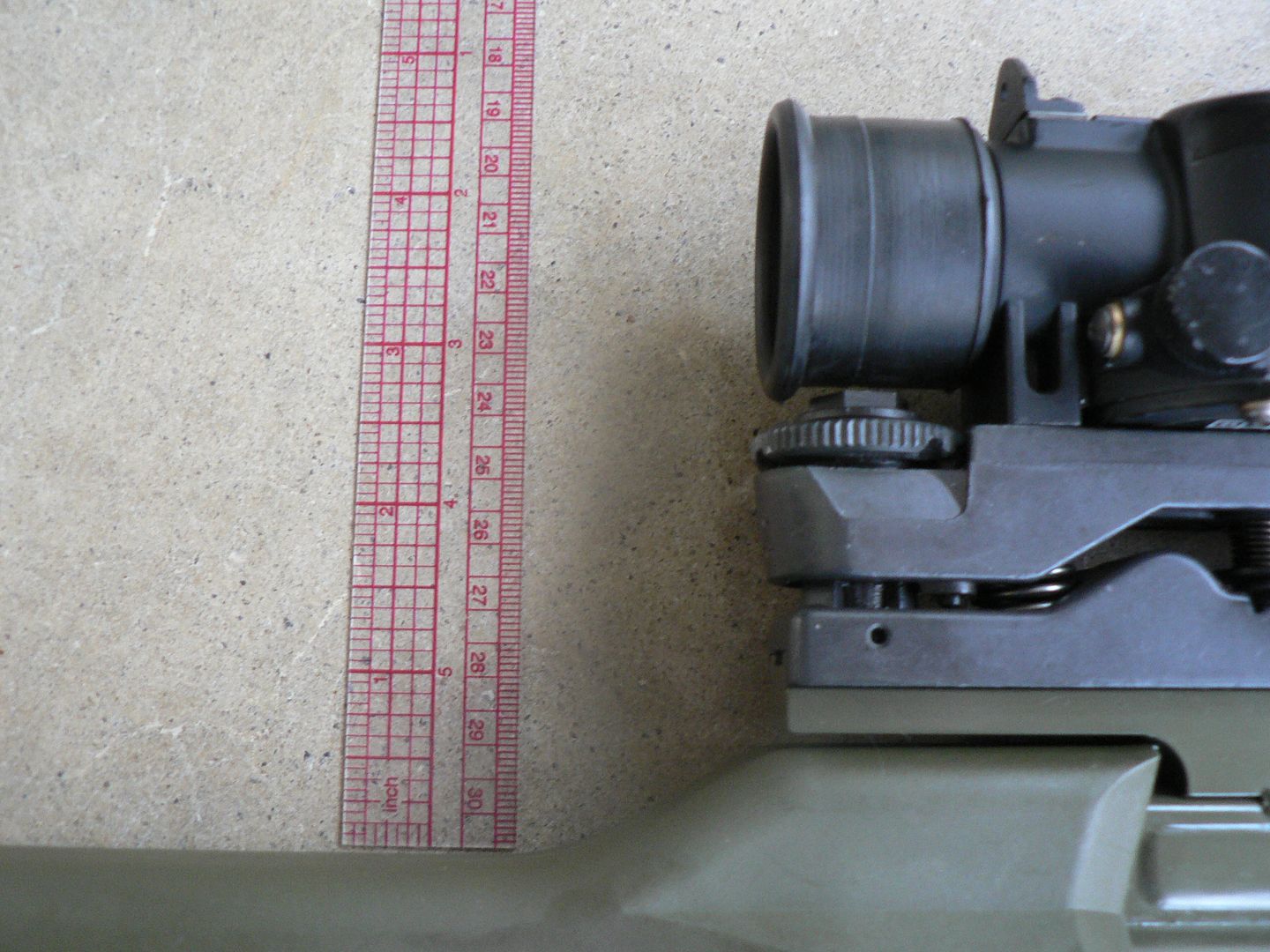
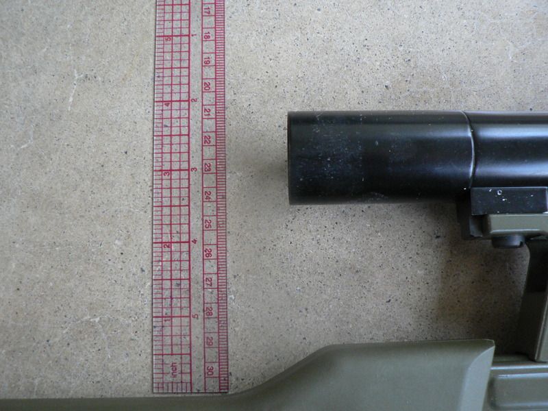
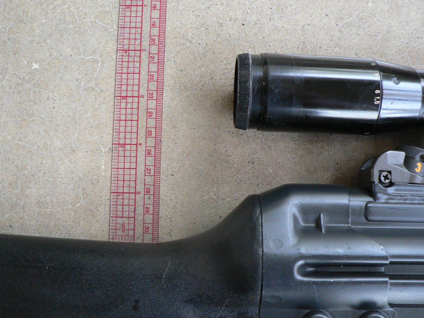
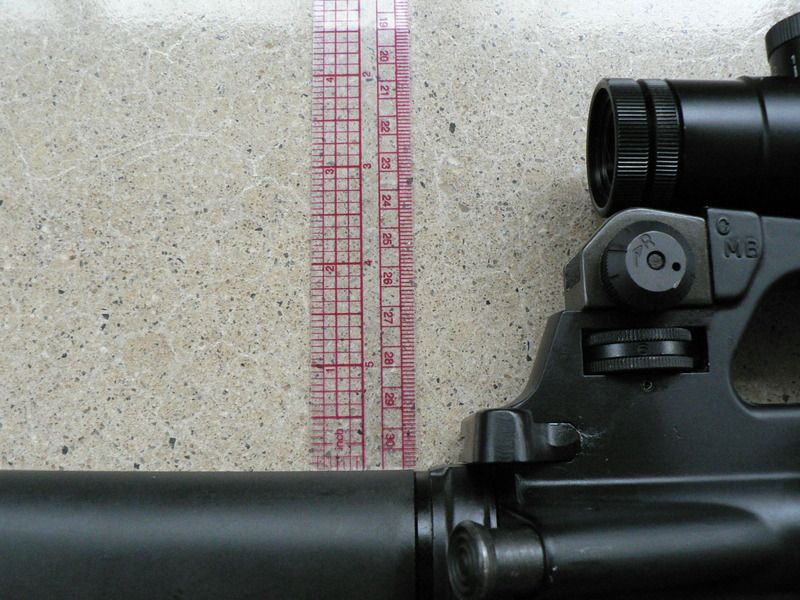
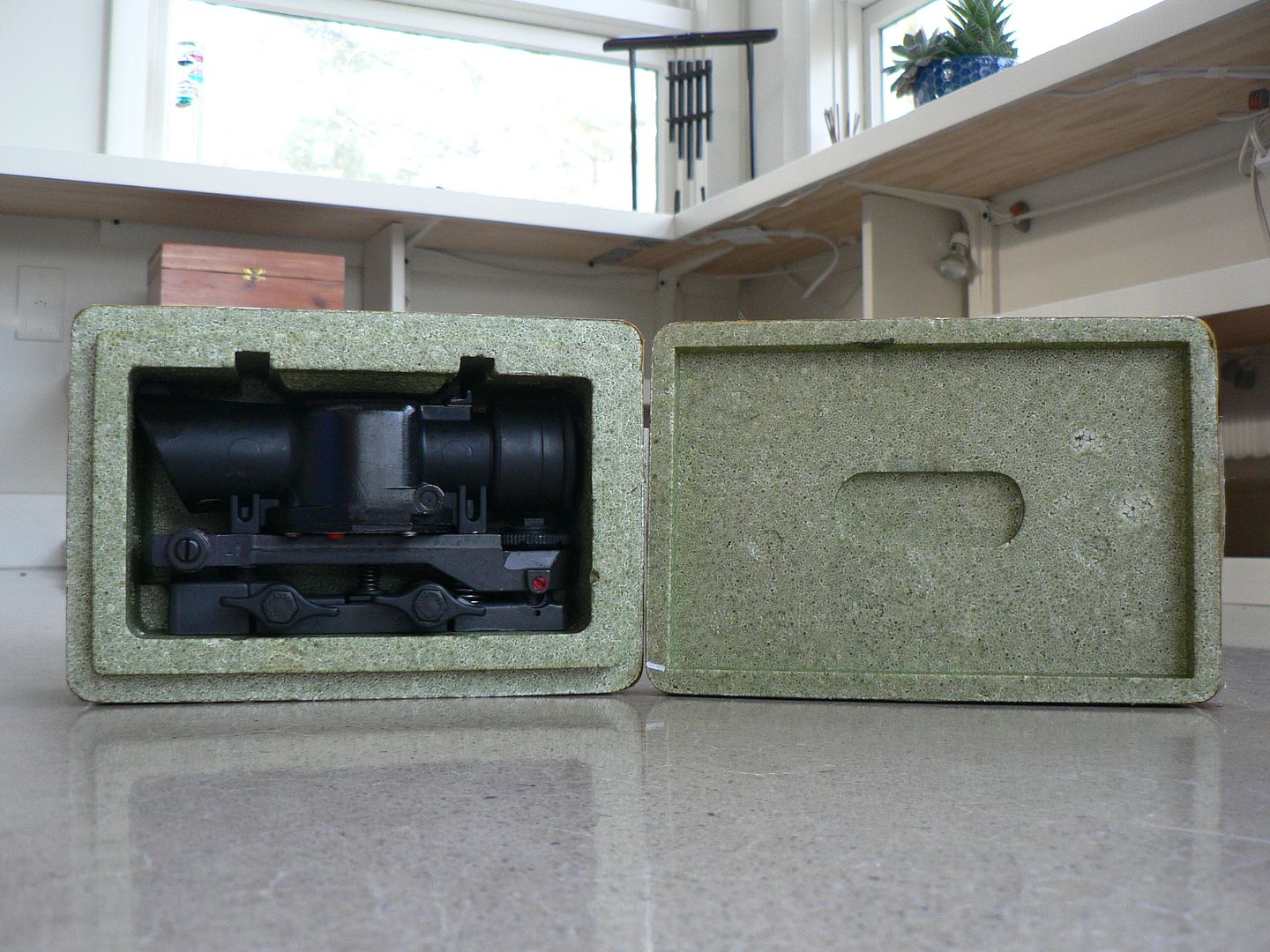
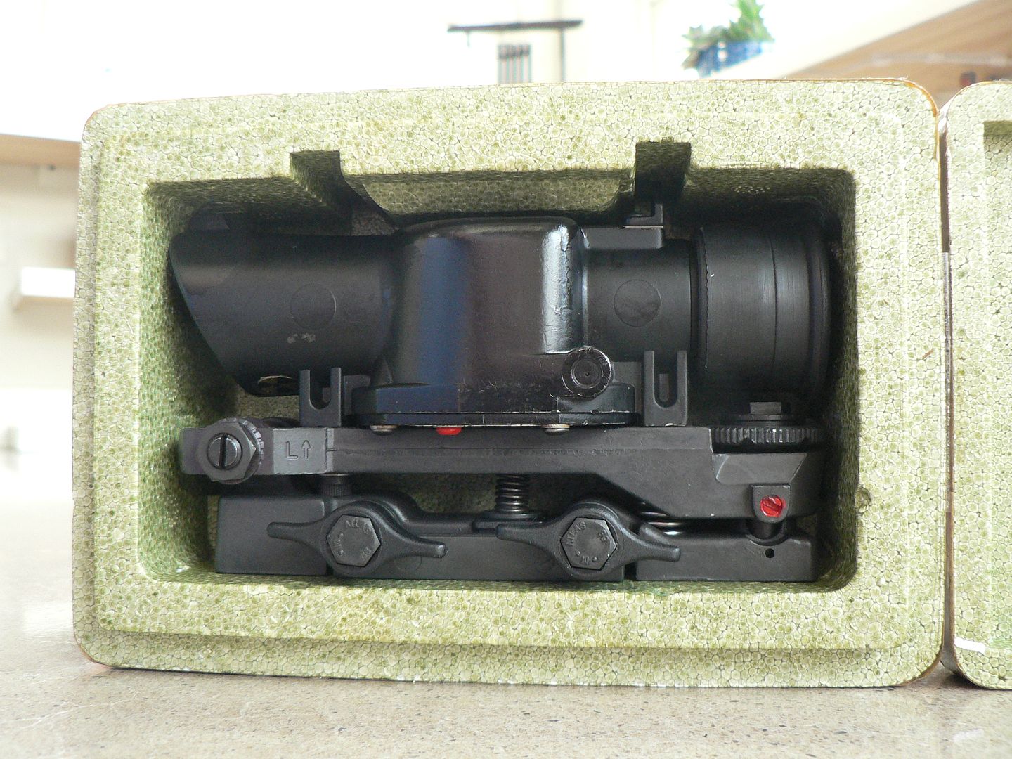
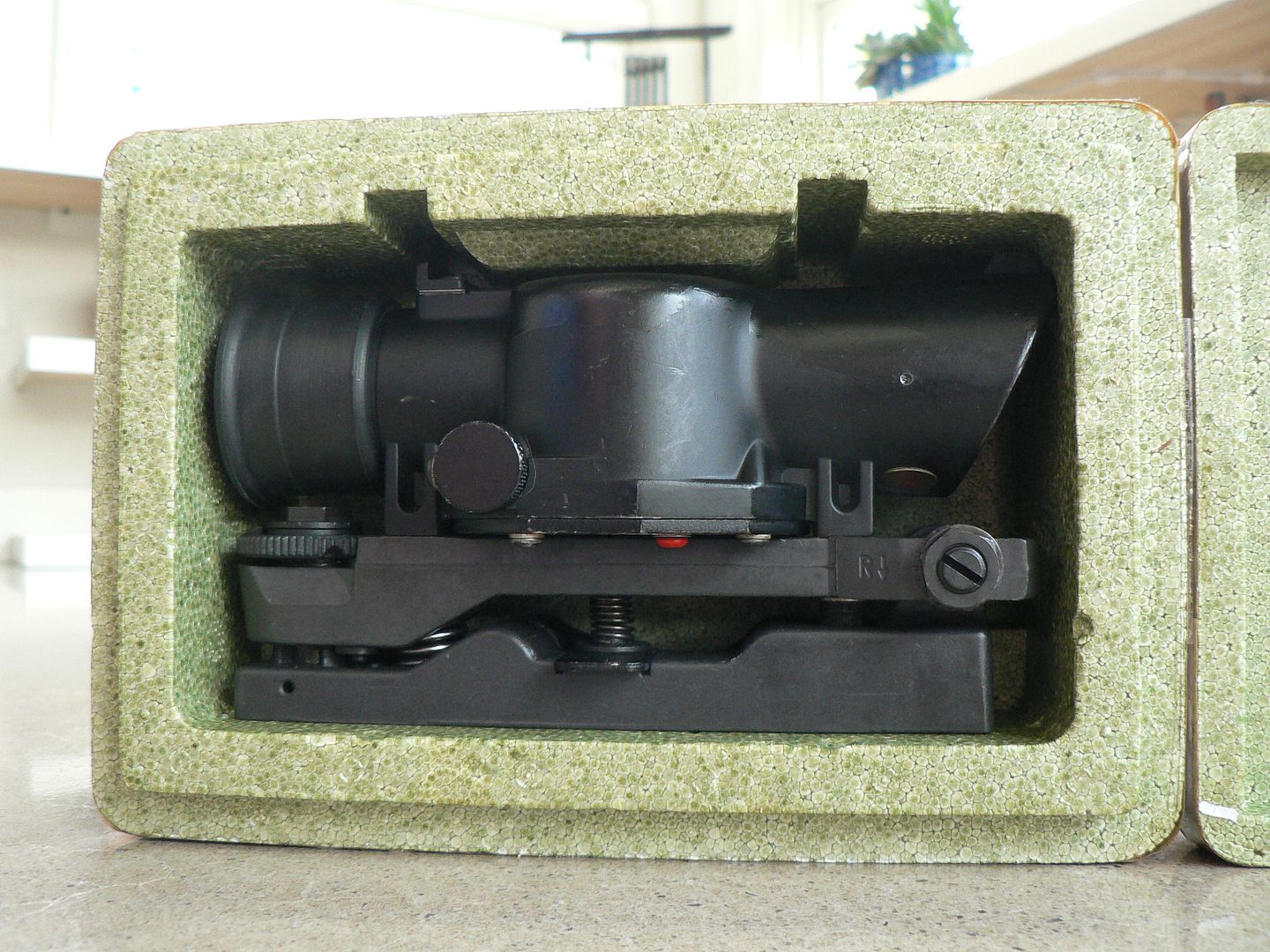
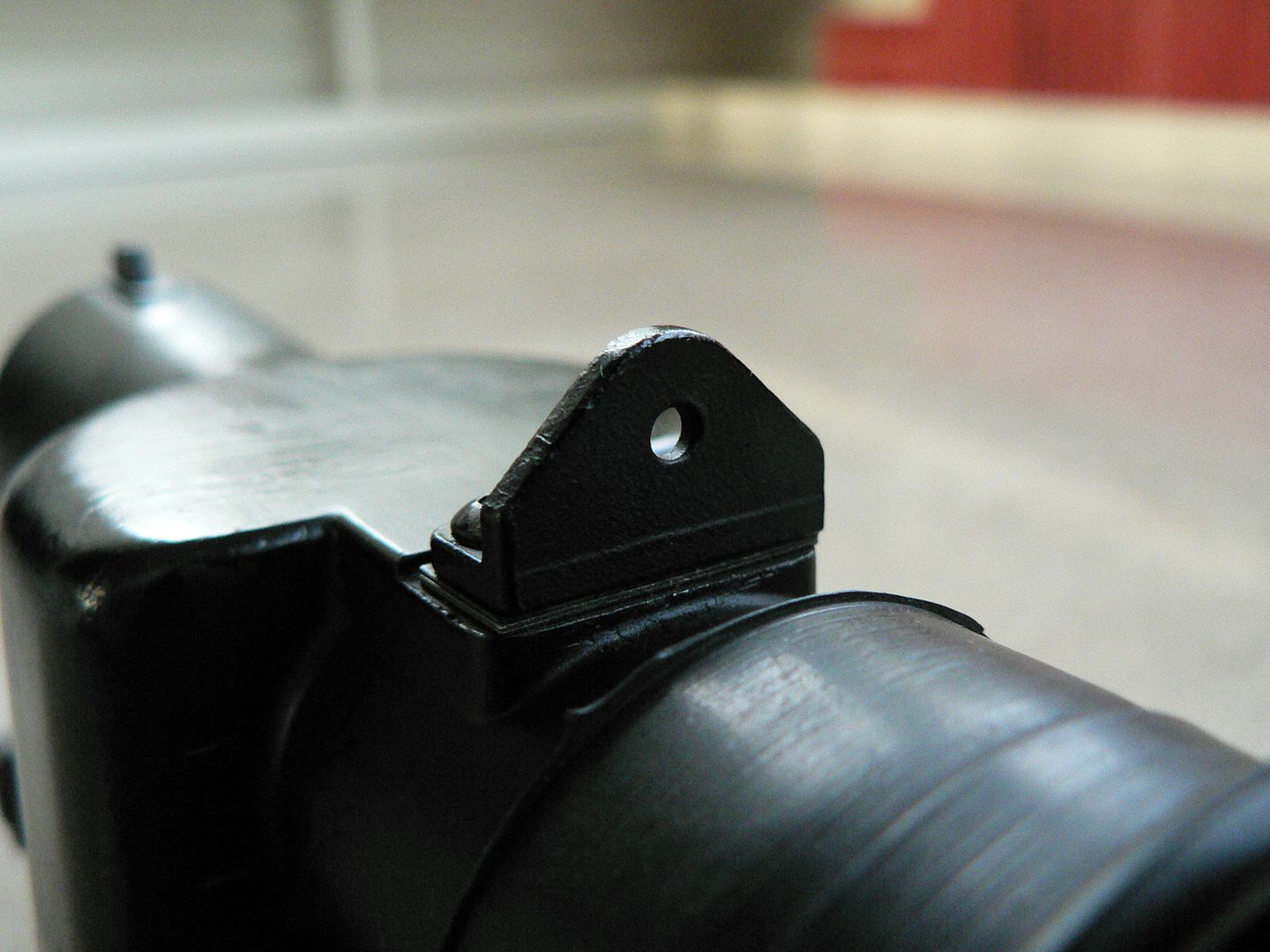
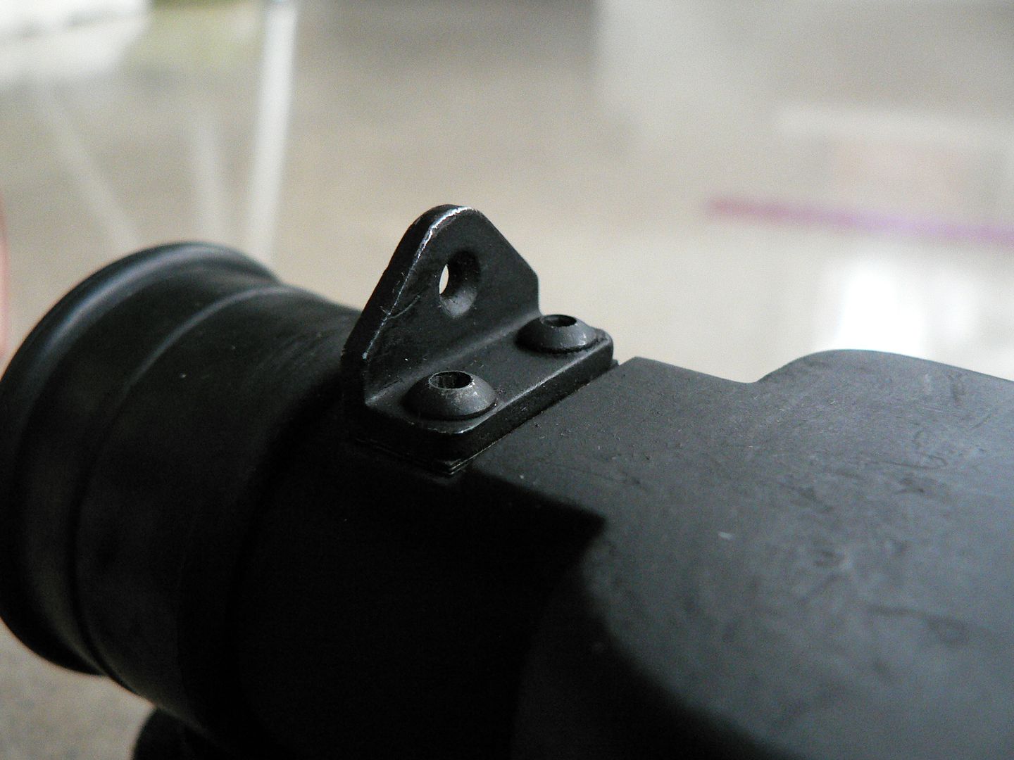
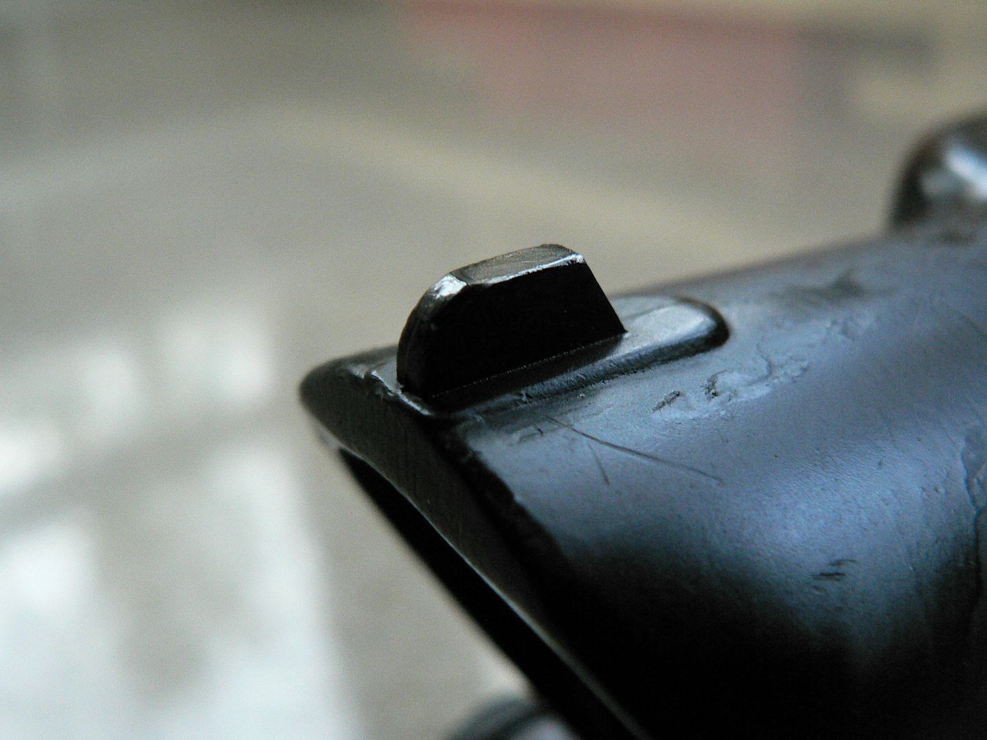
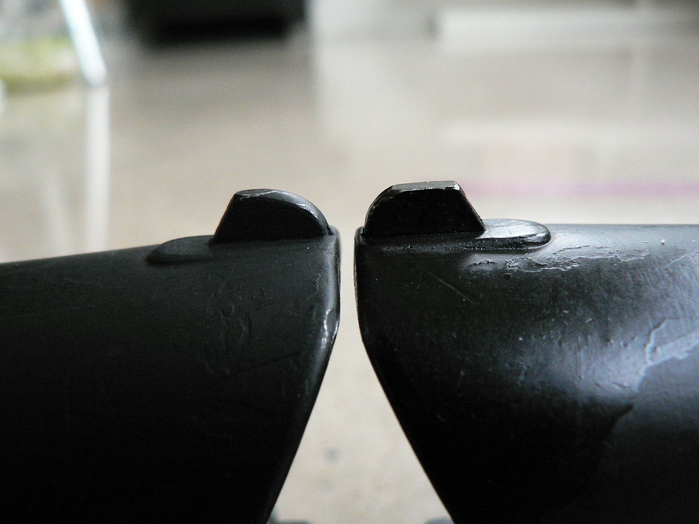
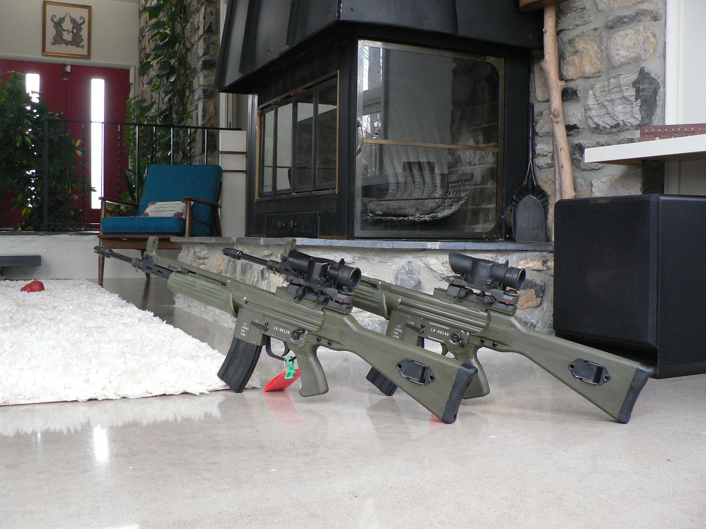
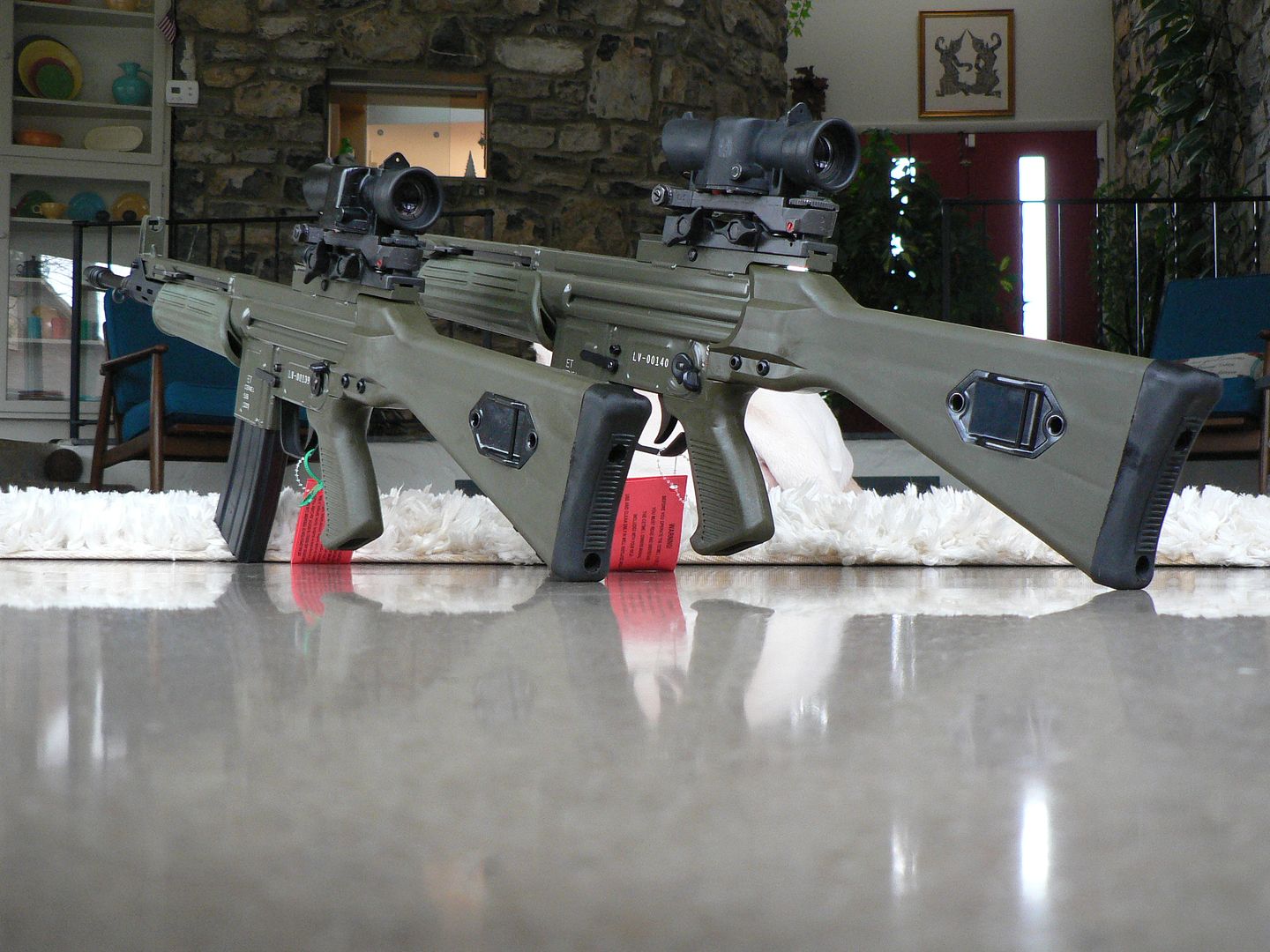
I just got my grubby hands on two of these jobbers today and wanted to give you folks a couple quick preview pictures of the upcoming LV/S reproduction by MarColMar. Rifles just like this were originally made for Spain's Unidad de Operaciones Especiales (UOE) or, in English, the Special Operations Unit. This coming weekend, I'll take some pictures and get to work on showing you guys what new treat MCM has cooked up. It looks like it should be pretty tasty!
Sasha said she wanted to be included in a picture too:
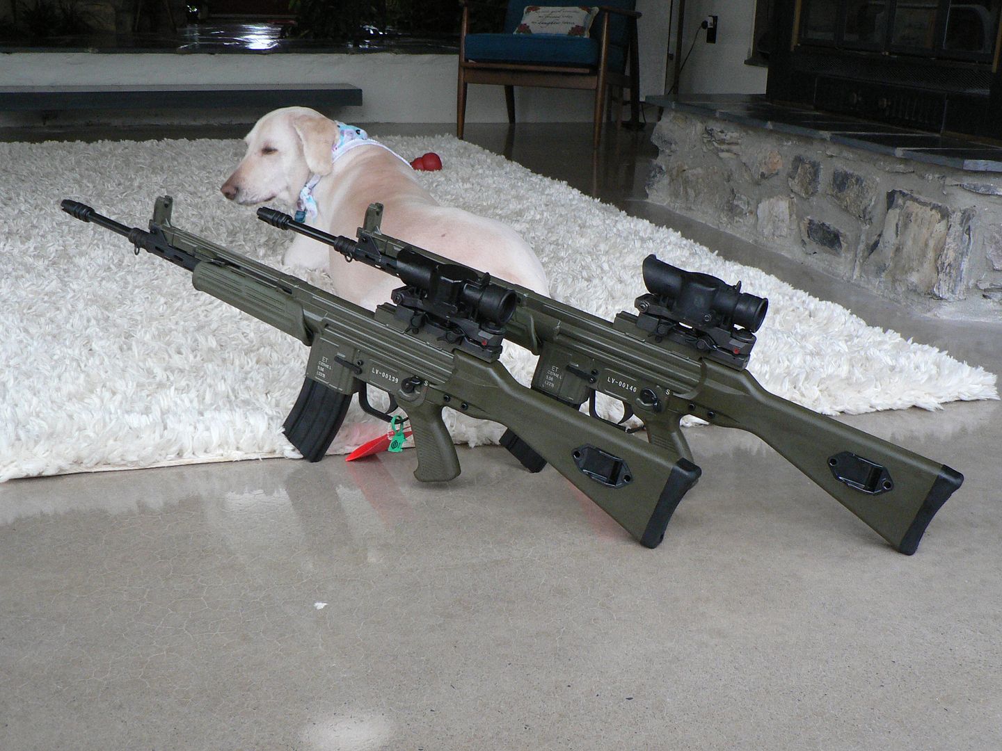
Sasha said she wanted to be included in a picture too: