Would any of these work?
http://www.mscdirect.com/browse/Cla...agnets/Alnico-Shielded-Magnets?navid=12101494
http://www.mscdirect.com/browse/Cla...agnets/Alnico-Shielded-Magnets?navid=12101494
Another possibility.. adhesive backed even!
http://www.mcmaster.com/#rare-earth-magnets/=nguwxe
aargh, link won't quite work.. click on the 'adhesive backed ultra high pull'
What would Countersinking the holes for Flat Head Screws do to the structure of the unit? Would it weaken it?
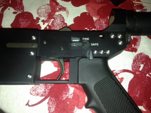
This is kind of sexy in an industrial erector set kind of way.
sent from somewhere in the world.


The 'thickness' of a #6 screw head is 0.094, so to set it flush or .005 below flush would leave you about .025 - .030" of hole without countersink. I honestly don't think that would be an issue, I'll look at this when I finish up the drawings and see how it looks. I like the idea of FH machine screws, would leave a neater overall outer appearance imo...All of the side plates are 1/8 (.125) thick. If you were to countersink the screw holes and use a countersunk screw it may work, but at the same time it may leave to little material to take the shock and vibration of firing. If you were to countersink it may leave a "knife edge" effect. All of the major aircraft manufactures suggest you leave .005 after countersinking. Without a screw to measure I can only guess how close it would be. This might be an idea for a MK2 design.
The 'thickness' of a #6 screw head is 0.094, so to set it flush or .005 below flush would leave you about .025 - .030" of hole without countersink. I honestly don't think that would be an issue, I'll look at this when I finish up the drawings and see how it looks. I like the idea of FH machine screws, would leave a neater overall outer appearance imo...
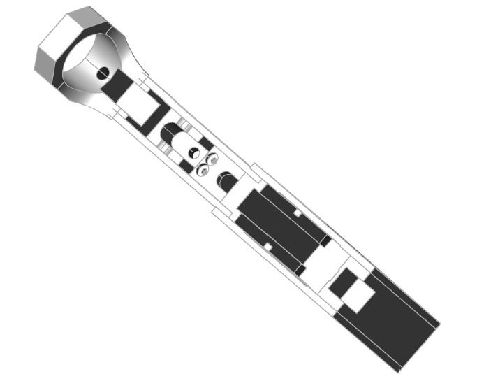
 (sorry, it plotted sideways... lol)

 I never thought this thread would take off like this and have 3,500 views! Im glad there are others out ther who like to think outside the box to make things. I can't wait to see the end product CAD design you guys are coming up with! Better yet, I cant wait to see a finished product!!!!
I like it! Function over form, I say... lol (especially with a safety device!)
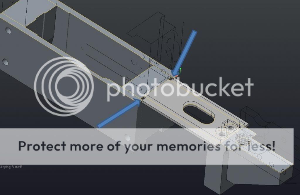
I have my modeling done, need a couple tweaks (found a pair of holes that don't quite line up, thinkin my dyslexia swapped a couple digits somewhere..
One other thing that has puzzled me, besides the small error that sst found, is why is this cutout going all the way to the rear of the part, leaving a little hole on either side of the magwell???
View attachment 91068
One other thing that has puzzled me, besides the small error that sst found, is why is this cutout going all the way to the rear of the part, leaving a little hole on either side of the magwell???
View attachment 91068
")